

Bioinformation measuring optical element and bioinformation measuring instrument using same
A technology of biological information and optical components is applied in the field of biological information measurement devices to achieve the effect of reducing interference
- Summary
- Abstract
- Description
- Claims
- Application Information
AI Technical Summary
Problems solved by technology
Method used
Image

Examples
Embodiment 1
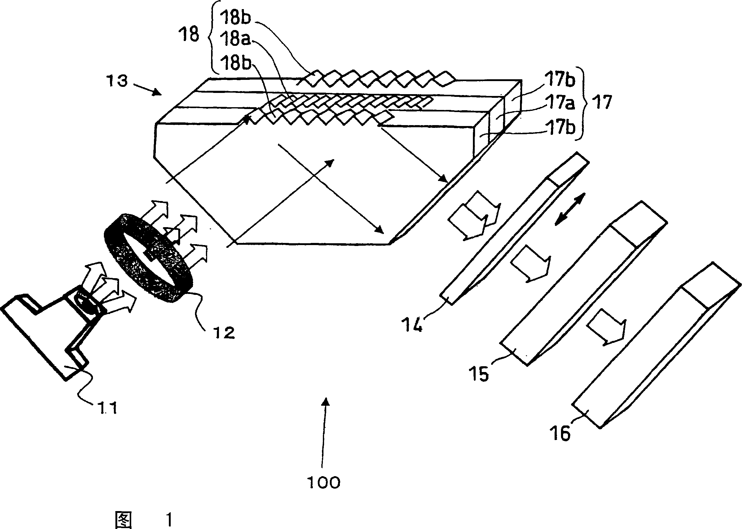
[0049] FIG. 1 is a schematic diagram of an optical element for measuring biological information and a biological information measuring device using the optical element in an embodiment of the present invention. As shown in FIG. 1 , a biological information measuring device 100 in this embodiment is formed with a light source 11 , an optical lens 12 , an optical element 13 for measuring biological information, a light separating device 14 , a spectroscopic device 15 and a light detecting device 16 .
[0050]The positional relationship between the light splitting device 14 and the spectroscopic device 15 is not limited to the positions shown in FIG. 1 . The light separating device 14 and the spectroscopic device 15 may be interposed between the light source 11 and the optical element 13 for measuring biological information. In the case where the spectroscopic device 15 and the light splitting device 14 are not used, the spectroscopic function can also be implemented by changing ...
Embodiment 2
[0107] As shown in FIG. 1 in Embodiment 1, the light passing through the first light-transmitting body 17 a , the second light-transmitting body 17 b and the third light-transmitting body 17 c may partially interfere with each other. In order to prevent interference more reliably, the optical element for measuring biological information in this embodiment is formed as shown in FIG. 7 .
[0108] FIG. 7 is a schematic diagram of the optical element 13 for measuring biological information in this embodiment and a biological information measuring device using the optical element. In FIG. 7, the light-shielding body 19 is located between the first light-transmitting body 17a and the two second light-transmitting bodies 17b. Based on this structure, the light-shielding body 19 prevents signals from the first light-transmitting body 17a and the second light-transmitting body 17b from interfering with each other, which is very preferable.
[0109] The light-shielding body 19 is prefe...
Embodiment 3
[0121] As a simpler structure of the optical element for measuring biological information in the present invention, a structure as shown in FIG. 9 is involved. FIG. 9 is a schematic diagram of an optical element 13 for measuring biological information in this embodiment and a biological information measuring device using the optical element.
[0122] In FIG. 9, the light-shielding body 19 is interposed between the first light-transmitting body 17a and the second light-transmitting body 17b. Based on this structure, the light-shielding body 19 prevents signals from the first light-transmitting body 17a and the second light-transmitting body 17b from interfering with each other, which is very preferable.
[0123] Other structures may be the same as those in Embodiment 1 or Embodiment 2 above.
[0124] The biological tissue measured by the optical element for measuring biological information and the biological information measuring device in the present invention is not particul...
PUM
| Property | Measurement | Unit |
|---|---|---|
| thickness | aaaaa | aaaaa |
| thickness | aaaaa | aaaaa |
| thickness | aaaaa | aaaaa |
Abstract
Description
Claims
Application Information