Eureka AIR delivers breakthrough ideas for toughest innovation challenges, trusted by R&D personnel around the world.

Liquid crystal display apparatus, portable device, and drive method for liquid crystal display apparatus

a technology of liquid crystal display and drive method, which is applied in the direction of electric digital data processing, instruments, computing, etc., can solve the problems of low visibility, inability to uniformize the potential of the opposing electrode over the entire screen, and increase power consumption

Inactive Publication Date: 2006-01-19
NEC LCD TECH CORP
View PDF6 Cites 89 Cited by
  • Summary
  • Abstract
  • Description
  • Claims
  • Application Information

AI Technical Summary

Benefits of technology

[0037] It is an object of the present invention to provide a liquid crystal display apparatus whose resolution does not drop when displaying different images to plural view points, a portable device equipped with the liquid crystal display apparatus, and a drive method for the liquid crystal display apparatus.

Problems solved by technology

As a user of the glass using type cannot avoid annoyance of wearing glasses, intensive studies have recently been made on the glass-less type which does not use glasses.
The parallax barrier type, when conceived, had the parallax barrier located between the pixels and the eyes, which brought about an annoyance and a low visibility.
The frame inversion drive method however has the following problem.
As capacitive coupling is made between the opposing electrode and the data line or the like and the opposing electrode itself has a resistance, it is difficult to make the potential of the opposing electrode uniform over the entire screen.
This undesirably increases power consumption.
The conventional technique however has the following problem.
Consequently, the visibility of character display significantly drops.
This problem becomes noticeable as the number of view points increases.
According to the prior art technologies concerning the stereoscopic image display apparatus, switching between stereoscopic display and two-dimensional display is carried out over the entire screen, and it is not possible to display a mixture of a stereoscopic image and a two-dimensional image at an arbitrary position.
A similar problem, which is not inherent only to the stereoscopic image display apparatus, generally occurs in display apparatuses which display images of plural view points.

Method used


Image

  • Liquid crystal display apparatus, portable device, and drive method for liquid crystal display apparatus
  • Liquid crystal display apparatus, portable device, and drive method for liquid crystal display apparatus
  • Liquid crystal display apparatus, portable device, and drive method for liquid crystal display apparatus

Examples


first embodiment

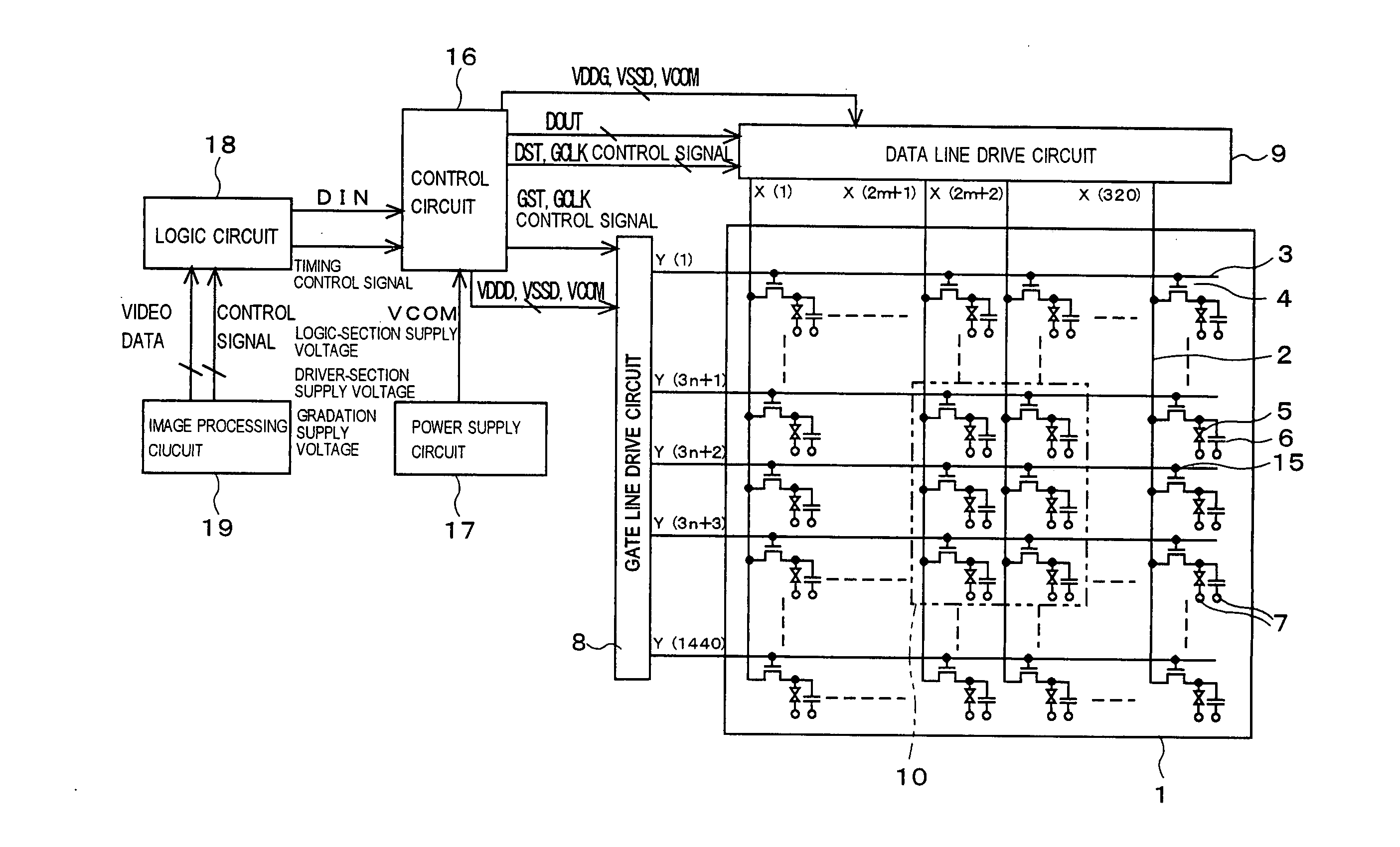
[0081] To begin with, the first embodiment of the present invention will be described. FIG. 9 is a block diagram of a liquid crystal display apparatus according to the present embodiment, FIG. 10 is a block diagram showing the relationship between the display pixels and sub pixels of a liquid crystal panel shown in FIG. 9, FIG. 11 is a top view showing the layout pitch of sub pixels of the liquid crystal display apparatus according to the present embodiment, and FIG. 12 is a perspective view showing an image display apparatus according to the present embodiment.

[0082] As shown in FIG. 9, the liquid crystal display apparatus according to the present embodiment is provided with a liquid crystal display panel 1, a gate line drive circuit 8 and a data line drive circuit 9, the latter two being connected to the liquid crystal display panel 1. A control circuit 16 is provided in such a way as to be connected to the gate line drive circuit 8 and the data line drive circuit 9. A power supp...

second embodiment

[0116] Next, the second embodiment of the present invention will now be explained. FIG. 16 is a block diagram illustrating the liquid crystal display panel of a liquid crystal display device according to the present embodiment. As shown in FIG. 16, the present embodiment differs from the first embodiment in that each of the display pixels 20 comprises twelve sub pixels. That is, band-like color filters of red, green, and blue which extend in the horizontal direction 12 are repeatedly provided on the liquid crystal panel 1 in the vertical direction 11 in the order of red, green, and blue. The lenticular lens (not shown) is provided in front of the liquid crystal panel 1. A plurality of cylindrical lenses which constitute the lenticular lens extend in the vertical direction 11, and one cylindrical lens corresponds to four sub pixels which are consecutively provided in the horizontal direction 12 in one display pixel.

[0117] As a result, in each display pixel 20, the red sub pixels R1 ...

third embodiment

[0122] Next, the third embodiment of the present invention will now be explained. FIG. 17 is a diagram of an optical model showing a liquid crystal display device according to the present embodiment. The present embodiment differs from the first embodiment in that the layout pitch of the display pixels in the liquid panel is different from that of the cylindrical lenses in the lenticular lens. That is, a plurality of display pixels are arranged in a matrix form on the liquid crystal panel, each display pixel is provided with six sub pixels, two display pixels arranged in the horizontal direction and three display pixels arranged in the vertical direction, as per the first embodiment. A backlight 44 is provided at the back of the liquid crystal panel 1.

[0123] As shown in FIGS. 11 and 17, given that the number of the sub pixels arranged in the vertical direction 11 in each display pixel is M, the number of the sub pixels arranged in the horizontal direction 12 is N, the layout pitch ...


PUM


Abstract

In a liquid crystal display apparatus, one display pixel has a total of six sub pixels, namely, a red sub pixel for a left eye, a green sub pixel for the left eye, a blue sub pixel for the left eye, a red sub pixel for a right eye, a green sub pixel for the right eye, and a blue sub pixel for the right eye. Those sub pixels are arranged in a square area, two in a horizontal direction along which gate lines extend, three in a vertical direction along which data lines extend. The polarity of the data lines with respect to a potential of a common electrode is inverted every time three gate lines are scanned and every frame.

Description

BACKGROUND OF THE INVENTION [0001] 1. Field of the Invention [0002] The present invention relates to a liquid crystal display apparatus in which display pixels each comprising a plurality of sub pixels are arranged in a matrix form, a portable device equipped with the liquid crystal display apparatus, and a drive method for the liquid crystal display apparatus. [0003] 2. Description of the Related Art [0004] Display apparatuses capable of displaying a stereoscopic image have been studied. As described in Literature “Three-dimensional Display” by Chihiro Masuda, published by Sangyo Tosho Publishing Co., Ltd., for example, Euclid, a Greek mathematician, contemplated in 280 B.C. that a stereoscopy is a feeling obtained as both the right and left eyes simultaneously see different images of a same object as seen from different directions. That is, a stereoscopic image display apparatus should have the function of providing the right and left eyes with images having parallax. [0005] As on...

Claims


Application Information

Patent Timeline
Patent Type & Authority Applications(United States)
IPC IPC(8): G09G5/00
CPCG09G3/003G09G3/3614H04N13/0404G09G2300/0452G09G3/3648H04N13/305
Inventor IRIGUCHI, MASAOIKEDA, NAOYASUUEHARA, SHIN-ICHI
Owner NEC LCD TECH CORP
Why Eureka
Eureka Blog
Learn More