Video/audio processor system, amplifier device, and audio delay processing method

Inactive Publication Date: 2006-01-19
SONY CORP
View PDF5 Cites 52 Cited by
  • Summary
  • Abstract
  • Description
  • Claims
  • Application Information

AI Technical Summary

Benefits of technology

[0020] Consequently, the amplifier device is able to acquire the processing-time information from the video processor apparatus when necessary. In addition, the providing unit of the video processor apparatus is able to directly acquire a processing state in the video signal processor, so that the audio signal can be delayed in the amplifier device in correspondence to a processing-objective video signal in the scan mode.
[0021]

Problems solved by technology

For example, with an Video/audio terminal device of a TV conference system, when processing and playing back a Video signal and audio signal being sent, the amount of data and of the Video signal is greater than that of the audio signal, and also the processing is relatively complex, so that outputting of video is delayed with respect outputting of audio, whereby there occurs an offset between audio and video inherently required to be accurately synchronized, consequently generating non-synchronous (or, asynchronous) audio and Video (event of the unmatch between audio and Video character's mouth movements), i.e., so-called lip sync error.
Thus, different f

Method used


Image

  • Video/audio processor system, amplifier device, and audio delay processing method
  • Video/audio processor system, amplifier device, and audio delay processing method
  • Video/audio processor system, amplifier device, and audio delay processing method

Examples


first embodiment

(Home Theater System)

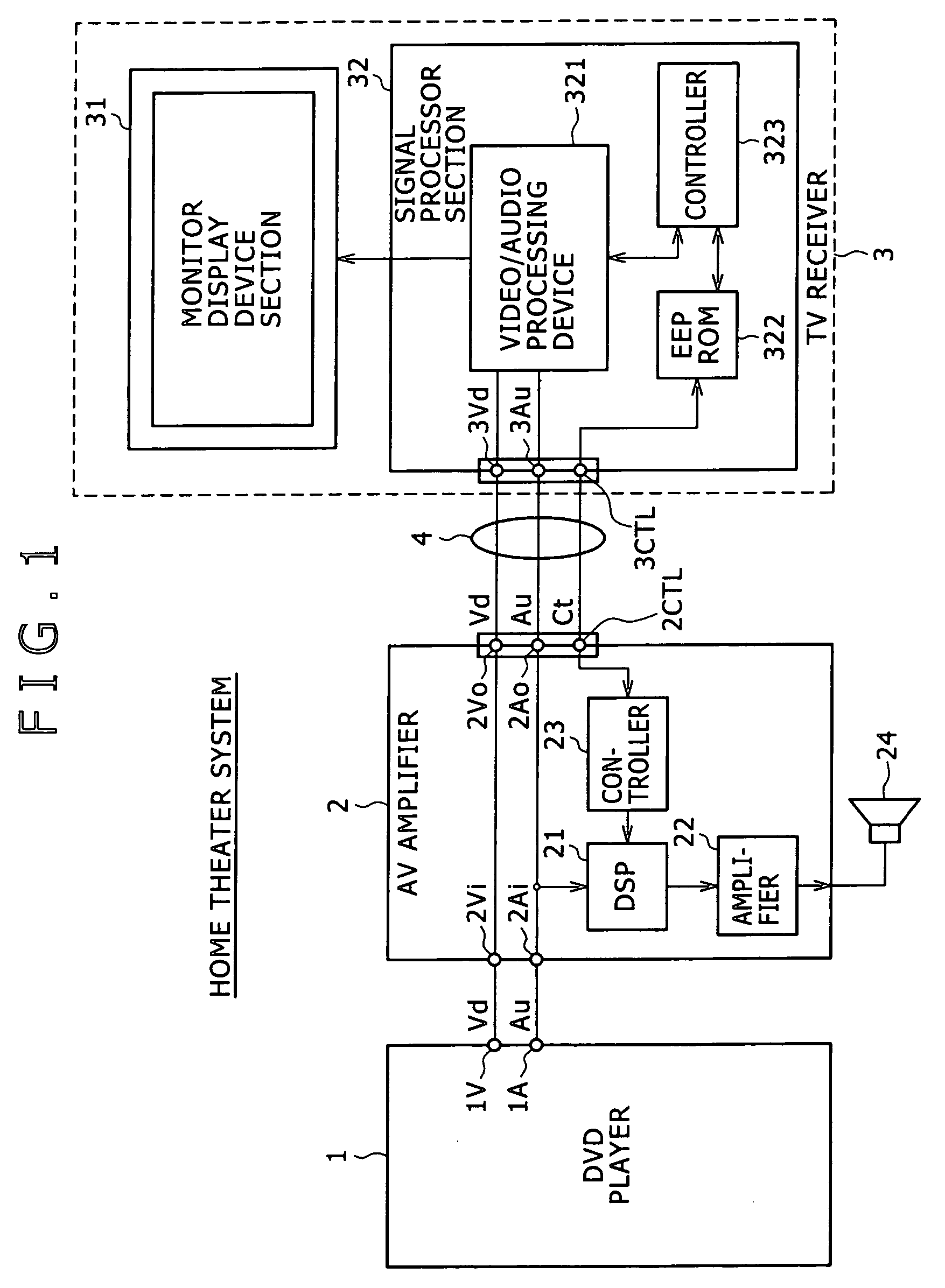
[0033]FIG. 1 is a block diagram descriptive of a home theater system in accordance with a first embodiment home theater system in accordance with a first embodiment. As shown in FIG. 1, home theater system in accordance with of the first embodiment is configured to include a DVD player 1, an AV amplifier 2, and a TV receiver 3. As described in more detail below, these devices are connected through predetermined digital interfaces.

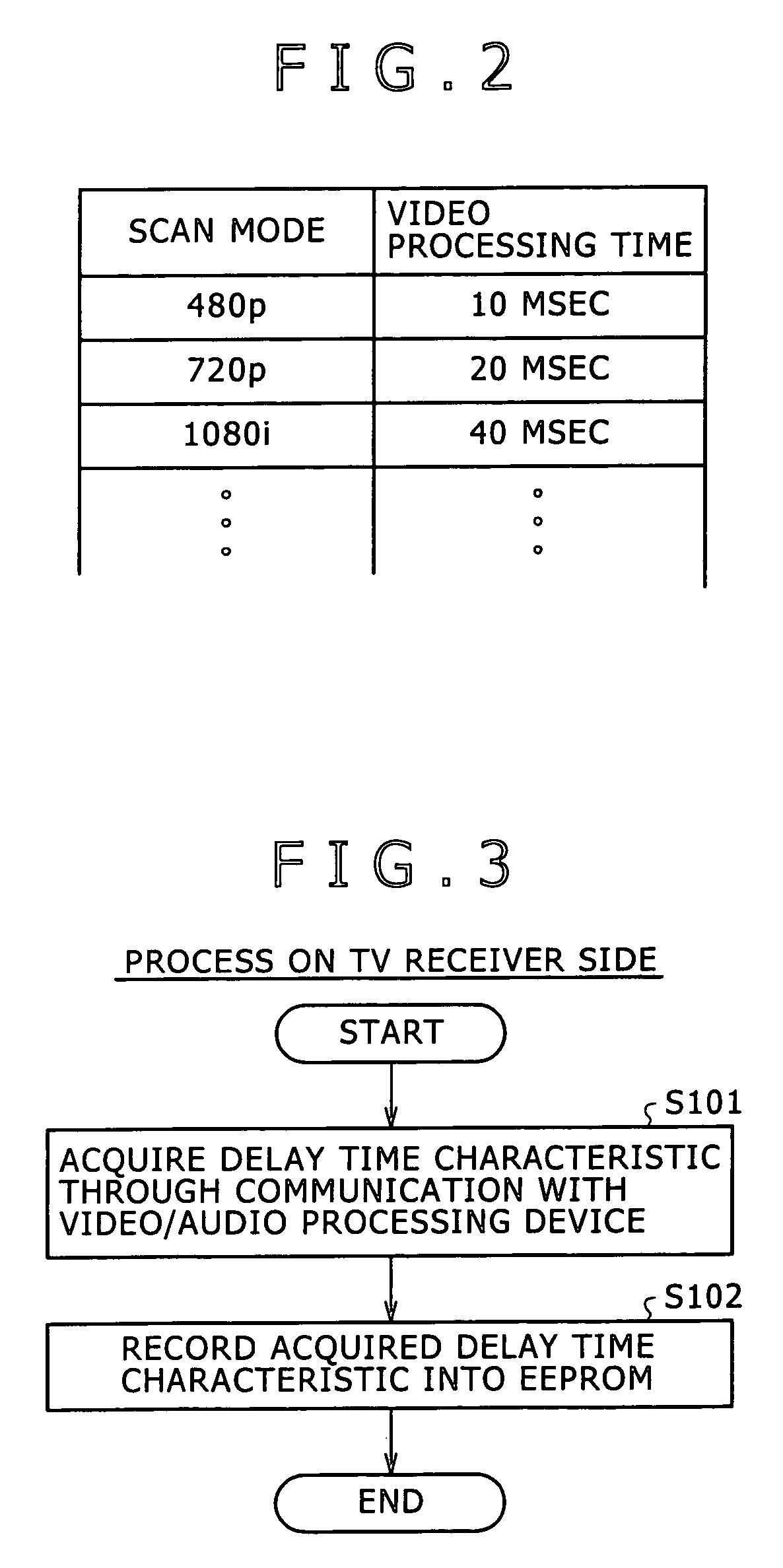
[0034] The DVD player 1 reads a video signal and an audio signal representing, for example, the contents of a movie recorded in a DVD, thereby to form output the video and audio signals and then to output them. In this case, the video signals include those of various modes depending on scan lines / offsetting techniques, such as a 480P (progressive scan technique (sequential scan technique) on a basis of 480 effective scan lines), 720P (progressive scan technique on a basis of 720 effective scan lines), and 1080 i (interlacing scan tec...

second embodiment

(Home Theater System)

[0069] A system, apparatus, and method according to a second embodiment of the invention will be described herebelow. FIG. 5 is a block diagram descriptive of a home theater system according to the second embodiment. As shown in FIG. 5, similarly as the home theater system according to the first embodiment shown in FIG. 1, the home theater system according to the second embodiment is configured to include the DVD player 1, the AV amplifier 2, and a TV receiver 5.

[0070] However, different from the TV receiver 3 used in the home theater system according to the first embodiment, the TV receiver 5 for use in the home theater system according to the second embodiment does not have the EEPROM 322 serving to provide the information to the AV amplifier 2. In the configuration of the second embodiment, communication is directly performed between a controller 522 of the TV receiver 5 and the controller 23 of the AV amplifier 2.

[0071] Thus, except that the TV receiver ...


PUM


Abstract

A system processes an audio signal and a video signal by using different devices, thereby preventing a so-called lip sync error. The processing time (represented by processing-time information) from the start of reception of a supplied video signal in a video processor apparatus to the start of displaying a video corresponding to the video signal on a display screen of a display device is acquired in an amplifier device from the video processor apparatus through a control signal line. In accordance with the acquired processing time, a delay processor delays processing of an audio signal supplied from the delay processor.

Description

CROSS-REFERENCE TO RELATED APPLICATIONS [0001] The present application claims priority from Japanese Patent Application No. JP 2004-209658 filed on Jul. 16, 2004, the disclosure of which is hereby incorporated by reference herein. BACKGROUND OF THE INVENTION [0002] The present invention relates to a Video / audio processor system having, for example, a Video processor apparatus such as a television (TV) receiver, and an AV (audio / Video) amplifier. The invention further relates to an amplifier device and an audio delay processing method for use with the video / audio processor system. [0003] For example, with an Video / audio terminal device of a TV conference system, when processing and playing back a Video signal and audio signal being sent, the amount of data and of the Video signal is greater than that of the audio signal, and also the processing is relatively complex, so that outputting of video is delayed with respect outputting of audio, whereby there occurs an offset between audio ...

Claims


Application Information

Patent Timeline
IPC IPC(8): H04N9/475H04N5/44H04N5/60
CPCG11B27/10H04N21/4341H04N21/2368H04N5/04
Inventor SASAKI, TAKASHI
Owner SONY CORP
Why Eureka
Try Eureka