Apparatus and methods for surface contour measurement

a surface contour and measurement apparatus technology, applied in the field of surface measurement, can solve the problems of moiré technique, inflexibility with respect to objects of different sizes, and difficulty in measuring surface contour information, so as to reduce the influence of speckle on measurement and mitigate the effect of speckl

Inactive Publication Date: 2006-01-19
MASSACHUSETTS INST OF TECH
View PDF24 Cites 35 Cited by
  • Summary
  • Abstract
  • Description
  • Claims
  • Application Information

AI Technical Summary

Benefits of technology

[0020] The invention also relates to a method for mitigating the effects of speckle on a measurement of a point on a surface of an object including the steps of projecting a coherent fringe pattern onto the surface of the object, providing a lens having a transmission function having a gradual transmission drop off at the lens edge, and detecting the fringe pattern in an image of the surface of the object, where the transmission function substantially reduces the speckle influence on the measurement.

Problems solved by technology

The measurement of surface contour information is an especially difficult problem in machine vision systems since depth information is often lost or is difficult to interpret.
One disadvantage of the moiré technique is its inflexibility with respect to objects of different sizes.
Due to this disadvantage, it is difficult to use a moiré technique for large-scale objects.
Another disadvantage of a moiré technique is that the resolution obtained using the technique may not be high enough for many applications
Although interferometric systems provide surface contour information, they are sensitive to vibrations in both the object being measured and the source of illumination being used.

Method used


Image

  • Apparatus and methods for surface contour measurement
  • Apparatus and methods for surface contour measurement
  • Apparatus and methods for surface contour measurement

Examples


Embodiment Construction

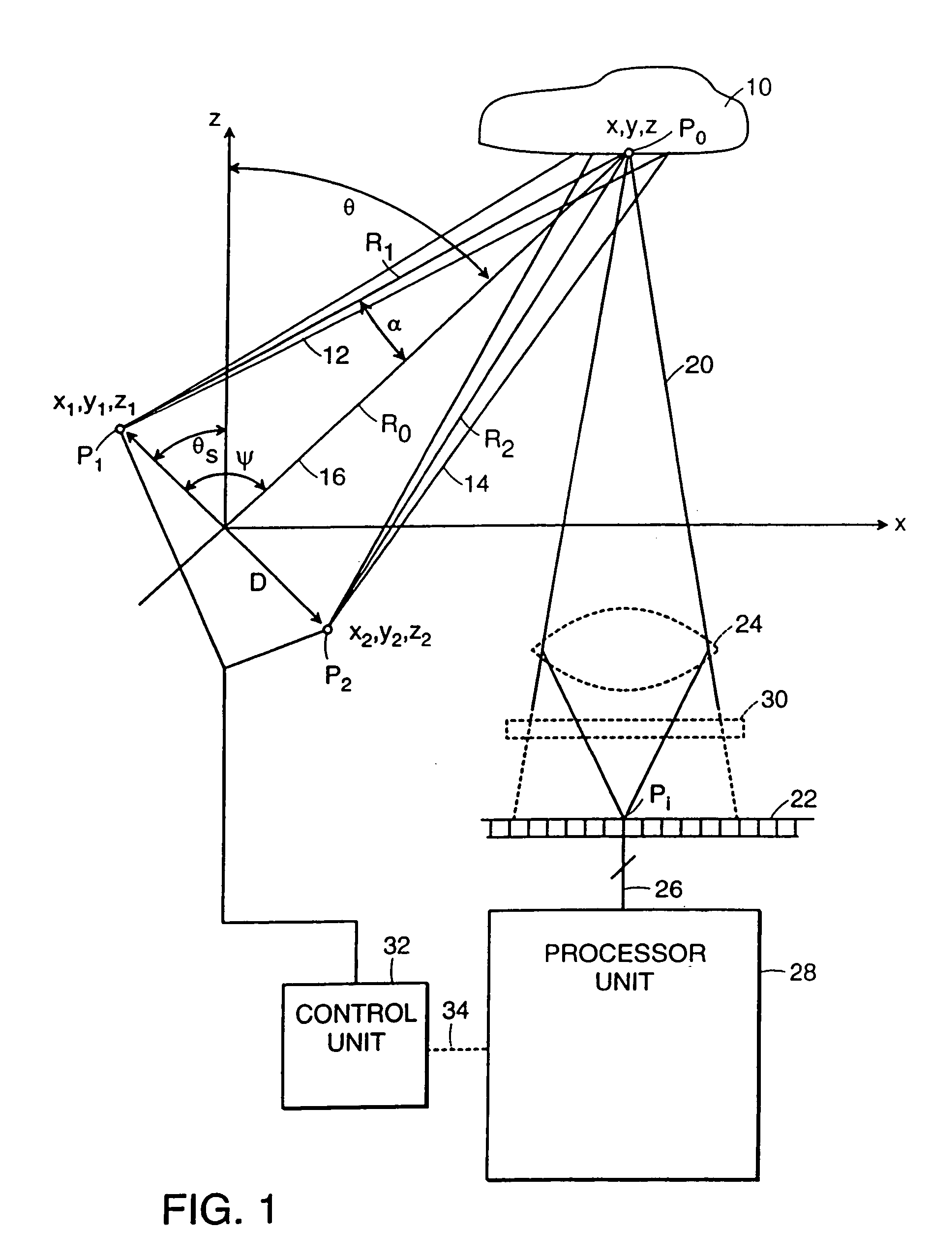
[0059] While describing the embodiment of the invention, reference will be made to “sources” and “sources of radiation.” These terms are meant to refer to any source of radiation, including highly localized sources of radiation.

[0060] Referring to FIG. 1, and in brief overview, two sources of radiation P1 and P2 are separated by a fixed distance D and have spatial coordinates of (x1,y1,z1) and (x2,y2,z2), respectively. The radiation from each of the sources P1 and P2 is coherent with respect to the radiation from the other one of the sources. Each source, P1 and P2, directs its respective divergent beam of radiation 12 and 14 toward a point P0 on the surface of an object 10. The distance from each respective source of radiation, P1 and P2, to the point on the surface P0 is indicated by R1 and R2, respectively. ψ is the angle between the line extending from the origin to the point P0 and the line extending between sources P1 and P2, θs is the angle between the z axis and the line ex...


PUM


Abstract

Apparatus and methods of measuring three-dimensional position information of a point on the surface of an object. The invention also relates to an apparatus for projecting fringes onto a surface of an object including two sources of radiation separated by a distance, each source having a spectral distribution, and being coherent with respect to the other of the sources, a control system moving each of the sources relative to the other of the sources, and a detector positioned to receive radiation scattered from the point on the surface of the object. In another embodiment, the two sources of radiation include, an initial source of a beam of radiation having a spectral width, a beam separator in optical communication with the initial source of a beam of radiation generating a first optical beam and a second optical beam, and an imaging system optically connected to the beam separator.

Description

CROSS-REFERENCE TO RELATED APPLICATIONS [0001] This application is a divisional of U.S. patent application Ser. No. 10 / 721,148 which was filed on Nov. 25, 2003 which is a continuation of U.S. patent application Ser. No. 09 / 480,043 which was filed on Jan. 10, 2000 which is a continuation-in-part of U.S. Pat. No. 6,031,612 which was filed on Feb. 2, 1999 and claims priority to provisional U.S. patent application No. 60 / 087,960 which was filed on Jun. 4, 1998. U.S. Pat. No. 6,031,612 is a continuation-in-part application of U.S. Pat. No. 5,870,191 which was filed on Feb. 12, 1996. The entireties of the above-referenced applications are incorporated by reference herein.[0002] Government Support [0003] Work described herein was supported by Federal Contract No: F19628-95-L-002, awarded by the United States Air Force. The Government may have certain rights in the invention.FIELD OF THE INVENTION [0004] The invention relates to the field of surface measurement and, more specifically, to th...

Claims


Application Information

Patent Timeline
Patent Type & Authority Applications(United States)
IPC IPC(8): G01B11/24G01B9/02G01B11/25
CPCG01B11/2531G01B11/2527
Inventor SHIRLEY, LYLE
Owner MASSACHUSETTS INST OF TECH
Why Eureka
Try Eureka