Acoustic fluid machine

a technology of acoustic fluid and acoustic pump, which is applied in the field of acoustic pump, can solve the problems of increasing the difficult to occur malfunction, and large cost of manufacturing the actuator, and achieves the effect of reducing the load

Inactive Publication Date: 2006-01-19
ANEST IWATA CORP
View PDF1 Cites 2 Cited by
  • Summary
  • Abstract
  • Description
  • Claims
  • Application Information

AI Technical Summary

Benefits of technology

[0006] In view of the disadvantages, it is an object of the present invention to provide an acoustic fluid machi

Problems solved by technology

The structure is simple and malfunction is difficult to occur.
However, in the acoustic fluid machine, a gas is sucked and discharged only by the piston which vibrates minutely, and there is a basic problem that co

Method used


Image

  • Acoustic fluid machine
  • Acoustic fluid machine
  • Acoustic fluid machine

Examples


first embodiment

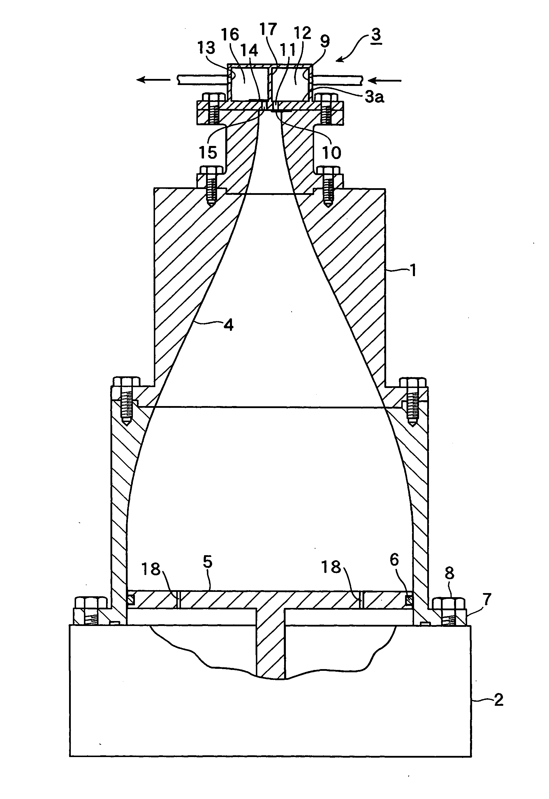
[0017]FIG. 1 shows a vertical sectional view of an acoustic fluid machine according to the present invention.

[0018] The acoustic fluid machine has an acoustic resonator 1, an actuator 2 at a larger-diameter base of the acoustic resonator 1, and a valve device 3 at the smaller-diameter upper end.

[0019] The acoustic resonator 1 has a resonant cavity 4 having the larger-diameter lower end and smaller-diameter upper end, and the resonant cavity 4 has an inner surface to comply with the following formula: r⁡(x)=rp-ro2⁢cos⁡(πL⁢x)+rp+ro2

where L is the length of the resonant cavity, rp is the radius of the lower end or base of the actuator and ro is the radius of the upper end or sucking or discharging upper end.

[0020] The actuator 2 is also a support, and has a piston 5 reciprocated by the actuator 2. The piston 5 is made of light alloy and fitted in the lower end of the resonant cavity 4. A seal 6 is fitted in the outer circumference of the piston 5. The acoustic resonator 1 has an ou...

second embodiment

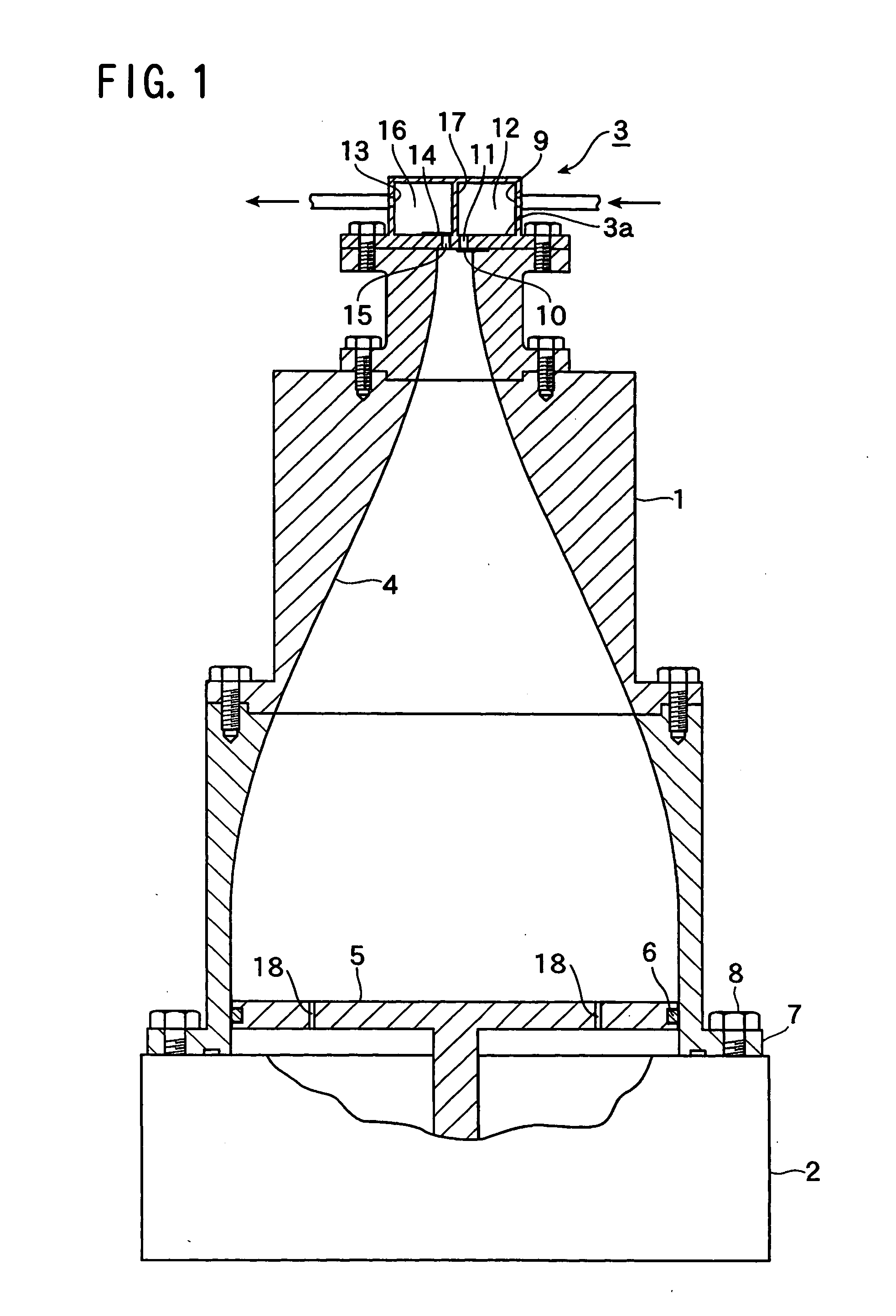
[0032]FIG. 2 is an enlarged vertical sectional view of the second embodiment according to the present invention, and FIG. 3 is a horizontal sectional view taken along the line III-III in FIG. 2. The basic structure is similar to that in FIG. 1, and only differences will be described.

[0033] A suitable number of grooves 19 are formed on the outer circumferential surface of a piston 5 and a seal 6 is provided on the inner surface of the acoustic resonator 1.

[0034] Through the grooves 19, front and rear spaces of the piston 5 communicate with each other, and the object of the invention can be achieved.

third embodiment

[0035]FIG. 4 is an enlarged vertical sectional front view of the present invention, and FIG. 5 is a horizontal sectional view taken along the line V-V in FIG. 4.

[0036] A recess 20 is formed on the outer circumferential surface of a piston 5, and a seal 6 is fitted in the inner circumferential surface of an acoustic resonator 1. Through the recess 5, front and rear spaces of the piston 5 communicate with each other, and the object of the invention can be achieved.


PUM


Abstract

An acoustic fluid machine has an acoustic resonator and a piston reciprocated by an actuator at the base of the acoustic resonator. A valve device is provided on the upper end of the acoustic resonator. External air is introduced into the acoustic resonator through the valve device. The piston has through-holes, through which front space communicates with rear space thereby reducing load applied onto the piston.

Description

BACKGROUND OF THE INVENTION [0001] The present invention relates to an acoustic fluid machine on the basis of acoustic resonance in an acoustic resonator. [0002] There is a known acoustic fluid machine in which a piston is reciprocated axially with minute amplitude at high speed in a larger-diameter base of an acoustic resonator so that a gas is sucked at the upper end into the acoustic resonator and discharged with pressure change in the acoustic resonator. [0003] The acoustic fluid machine is utilized by amplitude pressure change of acoustic standing waves generated by resonance with the piston that reciprocates axially with minute amplitude, and the piston in the base of the acoustic resonator is reciprocated at high speed by an actuator. [0004] The structure is simple and malfunction is difficult to occur. The acoustic fluid machine is expected to be used widely in the future. [0005] However, in the acoustic fluid machine, a gas is sucked and discharged only by the piston which ...

Claims


Application Information

Patent Timeline
IPC IPC(8): G01V1/145
CPCG01V1/133
Inventor KAWAHASHI, MASAAKIFUJIOKA, TAMOTSUSAITO, MASAYUKI
Owner ANEST IWATA CORP
Why Eureka
Try Eureka