
Distributed packet processing architecture for network access servers

a network access server and packet processing technology, applied in the field of packet data network access servers, can solve problems such as compromising the scalability of the architecture, and achieve the effects of increasing the number of concurrent users to be expanded, corresponding dsp resources, and increasing the number of ingress ports

Inactive Publication Date: 2006-01-19
CISCO TECH INC
View PDF7 Cites 54 Cited by
  • Summary
  • Abstract
  • Description
  • Claims
  • Application Information

AI Technical Summary

Benefits of technology

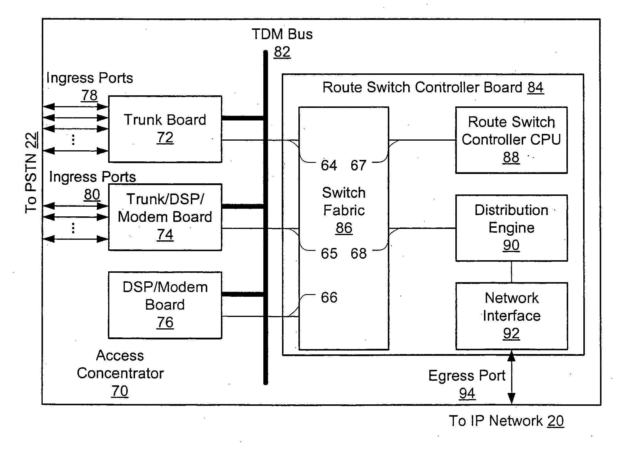
The patent describes a new access server architecture that improves scalability and balances processor load for a network access server device. The architecture allows for a distributed forwarding and packet processing amongst line cards, which increases the number of ingress ports and corresponding DSP resources. However, a potential bottleneck can develop at the egress port(s) with this distributed concept. To address this, the disclosed embodiments describe a new method that allows each line card to perform packet processing and forwarding for packets received at the egress port, while also using a distribution engine to decrease the computational power needed at the egress port. This results in a more scalable and efficient access server.

Problems solved by technology

Were a single forwarding engine deployed for all packets received at the egress port, this engine would in all probability have to perform packet processing on over half of all packets traversing the access server, once again compromising the scalability of the architecture.

Method used


Image

  • Distributed packet processing architecture for network access servers
  • Distributed packet processing architecture for network access servers
  • Distributed packet processing architecture for network access servers

Examples


Embodiment Construction

[0027] Several embodiments are described below. These embodiments refer to several existing protocols, standards, and particular component devices useful in practicing the invention. These references are merely exemplary, as those of ordinary skill will appreciate that various alternatives and equivalents are available.

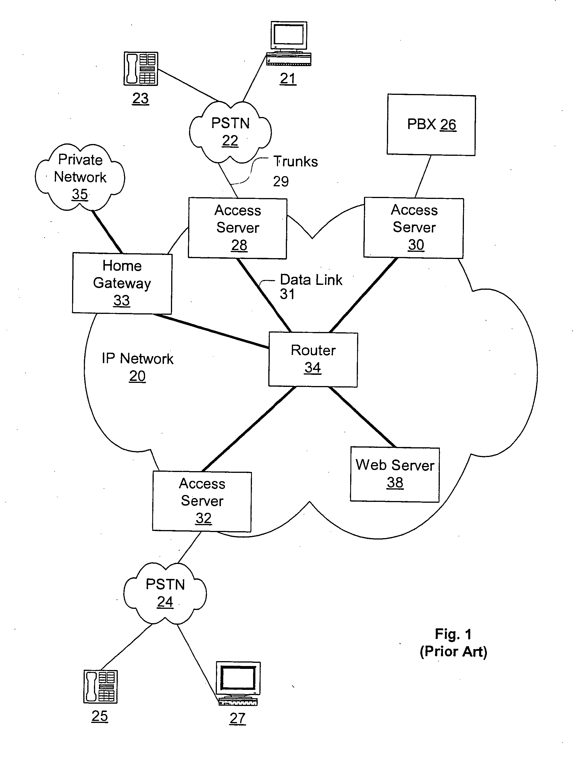
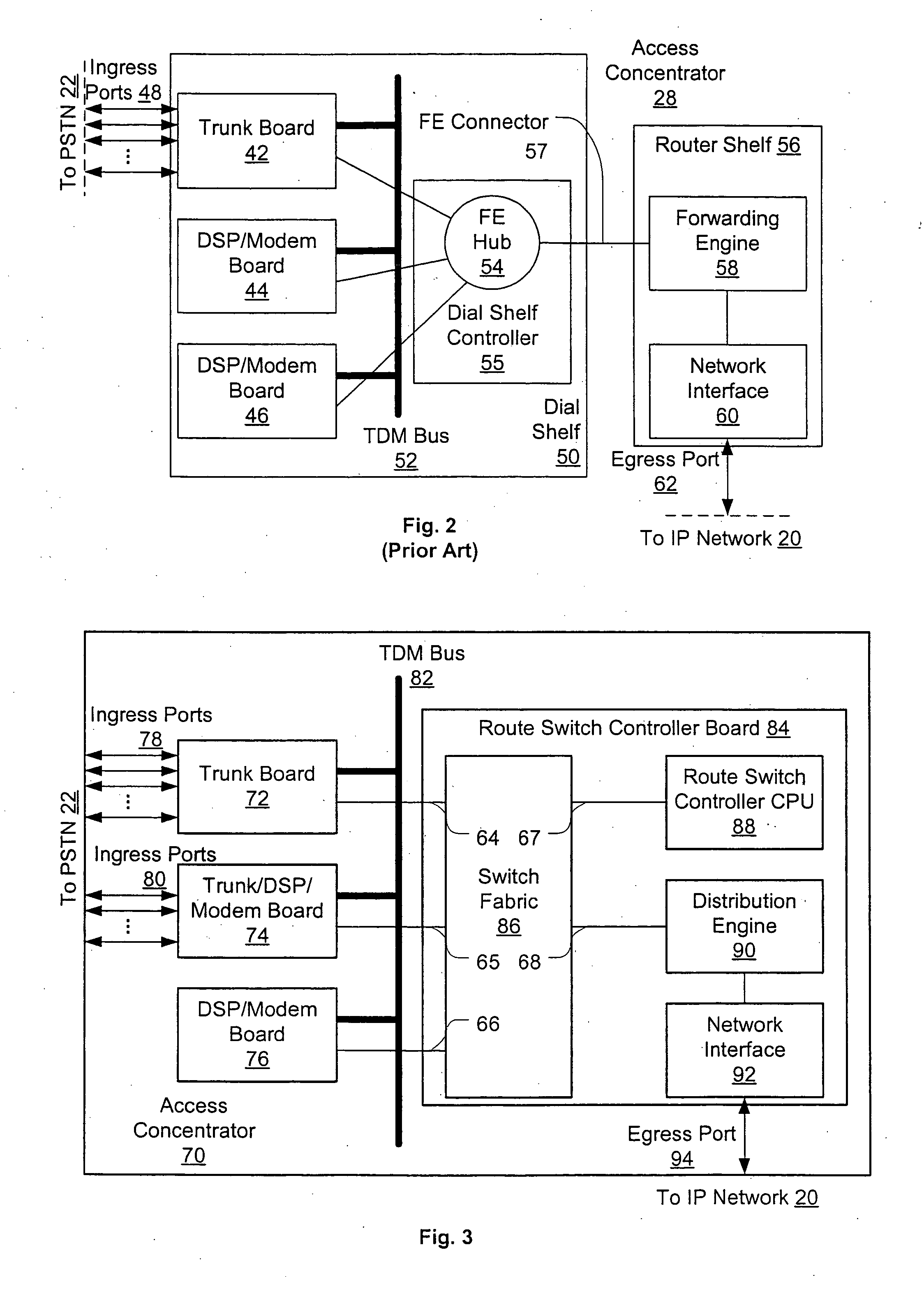
[0028] As an introduction, FIG. 1 illustrates a prior art deployment of network access servers. Access server 28 connects to PSTN 22 via one or more PSTN trunks 29, where each trunk is, e.g., a T1, T3, or E1 time-division-multiplexed (TDM) trunk, an ISDN Primary Rate Interface (PRI), or some equivalent. The access server users themselves (a computer user 21 and a telephone user 23 are shown) connect to PSTN 22, which provides physical connectivity to access server 28 via trunks 29. Depending on trunk capacity and utilization, each trunk will allow some number of additional users to reach IP network 20 through access server 28, for example, each added T1 connection al...


PUM


Abstract

An access server architecture, and methods for use of the architecture, are disclosed. The architecture and methods are designed to increase the scalability of and balance processor load for a network access server device. In this architecture, packet forwarding and packet processing are distributed amongst the cards serving the low-speed access lines (i.e., line cards), such that each line card is responsible for performing forwarding and packet processing for packets associated with the low-speed ports that line card serves. Thus, as the number of line cards expands, forwarding resources are expanded in at least rough proportion. The NAS route switch controller, as well as the high-speed ports used to access the network, are largely relieved of packet processing tasks for traffic passing through the server. The egress port uses a distribution engine that performs a cursory examination on one or more header fields on packets received at the high-speed interface-comprehending only enough information to allow each packet to be distributed to the appropriate line card for full packet processing. The route switch controller updates the routing information needed by each distribution or forwarding engine, and is largely uninvolved in the processing of individual packets.

Description

CROSS REFERENCE TO RELATED APPLICATIONS [0001] This application is a continuation of U.S. patent application Ser. No. 09 / 735,280, filed Dec. 11, 2000, now U.S. Pat. No. ______.FIELD OF THE INVENTION [0002] This invention pertains generally to packet data network access servers, and more particularly to methods and apparatus for performing distributed packet processing within such an access server. BACKGROUND OF THE INVENTION [0003] In the data communications field, a packet is a finite-length (generally several tens to several thousands of octets) digital transmission unit comprising one or more header fields and a data field. The data field may contain virtually any type of digital data. The header fields convey information (in different formats depending on the type of header and options) related to delivery and interpretation of the packet contents. This information may, e.g., identify the packet's source or destination, identify the protocol to be used to interpret the packet, i...

Claims


Application Information

Patent Timeline
Patent Type & Authority Applications(United States)
IPC IPC(8): H04L12/28H04L12/56
CPCH04L45/583H04L45/00
Inventor MA, STEPHENSANGIAH, SURESHTANGIRALA, JAGANNADHARMISTEAD, R. ASHBY
Owner CISCO TECH INC
Learn More