Radio communication apparatus, base station and system

a radio communication and base station technology, applied in the direction of multiplex communication, wireless communication, orthogonal multiplex, etc., can solve the problem of difficult suppression of the occurrence itself of interference, weak possibility of transmission error, and inability to acquire information concerning the entire band of transmission signals of the base station at a tim

Inactive Publication Date: 2006-01-19
KK TOSHIBA
View PDF25 Cites 190 Cited by
  • Summary
  • Abstract
  • Description
  • Claims
  • Application Information

AI Technical Summary

Benefits of technology

[0010] In accordance with a first aspect of the invention, there is provided a radio communication apparatus for receiving an orthogonal frequency division multiplexing (OFDM) signal from a base station and transmitting a frequency hopping (FH) signal to the base station, using a plurality of sub-channels, the base station comparing a plurality of hopping pattern information items indicating hopping patterns from a plurality of radio communication apparatuses including the radio communication apparatus, and generating collision information when the hopping patterns include colliding hopping patterns, the apparatus comprising: an estimation unit configured to estimate a plurality of channel response ...

Problems solved by technology

In this case, during the time spent for a sub-channel of a degraded propagation environment, the possibility of occurrence of a transmission error is strong.
However, in the above prior art in which interference is avoided by changing a frequency-hopping pattern, it is difficult to suppress the occurrence itself of interference where the interference is caused by, for example, a transmitter that uses the same frequency-hopping pattern as the currently used one.
However, if signals are transmitted from the mobile station utilizing ...

Method used


Image

  • Radio communication apparatus, base station and system
  • Radio communication apparatus, base station and system
  • Radio communication apparatus, base station and system

Examples


first embodiment

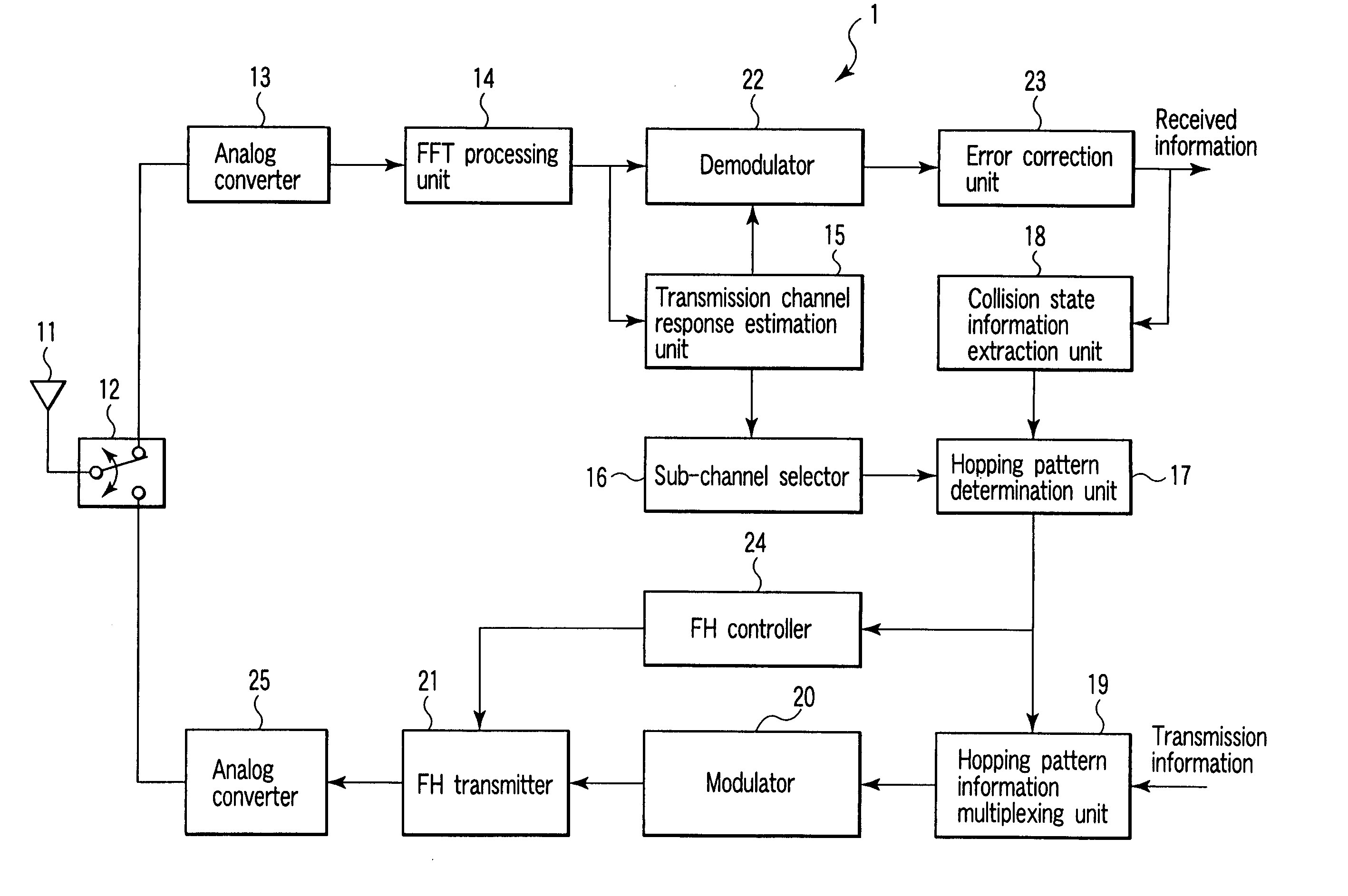
[0073] Referring to the block diagram of FIG. 5, a description will be given of a radio communication apparatus (mobile station 1) according to a first embodiment.

[0074] The mobile station 1 of this embodiment determines a frequency-hopping pattern from sub-channels of a good propagation environment based on a signal supplied from the base station 2, and performs transmission using the determined frequency-hopping pattern. The mobile station 1 comprises an OFDM receiver and HF transmitter. As shown in FIG. 5, the mobile station 1 comprises an antenna 11, antenna duplexer 12, analog converter 13, FFT (fast Fourier transform) processing unit 14, transmission channel response estimation unit 15, sub-channel selector 16, hopping pattern determination unit 17, collision state information extraction unit 18, hopping pattern information multiplexing unit 19, modulator 20, FH transmitter 21, demodulator 22, error correction unit 23, FH controller 24 and analog converter 25.

[0075] The ante...

second embodiment

[0111] Referring now to FIG. 12, a description will be given of a radio communication apparatus (mobile station 1) according to a second embodiment of the invention.

[0112] The mobile station 1 of the second embodiment selects sub-channels of a good propagation environment based on a signal from the base station 2, and transmits the selected sub-channels to the base station 2. The base station 2 determines the respective frequency-hopping patterns of the mobile stations 1 based on sub-channels of a good propagation environment. Using the determined frequency-hopping patterns, the mobile stations 1 perform FH-scheme communication.

[0113] The mobile station 1 of the second embodiment differs from that of the first embodiment in that in the second embodiment, each mobile station 1 does not determine a frequency-hopping pattern, and performs FH-scheme communication based on hopping pattern information supplied from the base station 2. In the first and second embodiments, like reference ...

third embodiment

[0136] Referring to FIG. 16, a radio communication apparatus (mobile station 1) according to a third embodiment will be described.

[0137] The mobile station 1 according to the third embodiment detects a frequency-hopping pattern used by another mobile station 1, thereby determining a frequency-hopping pattern formed of sub-channels that are not incorporated in the detected frequency-hopping pattern.

[0138] The third embodiment differs from the first embodiment wherein the base station detects the collision state of frequency-hopping patterns. That is, in the third embodiment, each mobile station 1 detects the frequency-hopping pattern of another mobile station 1, thereby finding out unused sub-channels and incorporating the unused sub-channels in a frequency-hopping pattern. In the first and third embodiments, like reference numerals denote like elements, and duplication of explanation will be avoided. The mobile station 1 of the third embodiment employs a power-measuring unit 61 in...


PUM


Abstract

Radio communication apparatus for receiving OFDM signal from base station and transmitting FH signal to base station, using sub-channels, base station comparing hopping pattern information items indicating hopping patterns from radio communication apparatuses including radio communication apparatus, and generating collision information when hopping patterns include colliding hopping patterns, includes estimation unit configured to estimate channel response values of sub-channels based on OFDM signal, selector which selects, from sub-channels, several sub-channels which have higher channel response values than a value, each of channel response values being expressed by power level, signal-to-noise power ratio, or signal-to-interference ratio, determination unit configured to determine hopping pattern from selected sub-channels, transmitter which transmits, to base station, hopping pattern information item indicating determined hopping pattern, receiver which receives collision information from base station, and correction unit configured to correct hopping pattern based on collision information.

Description

CROSS-REFERENCE TO RELATED APPLICATIONS [0001] This application is based upon and claims the benefit of priority from prior Japanese Patent Application No. 2004-210196, filed Jul. 16, 2004, the entire contents of which are incorporated herein by reference. BACKGROUND OF THE INVENTION [0002] 1. Field of the Invention [0003] The present invention relates to a radio communication apparatus, base station and system utilizing time division duplex (TDD), in which orthogonal frequency division multiplexing (OFDM) is used for signals (down-signals) transmitted from the base station to the radio communication apparatus, and frequency hopping (FH) is used for signals (up-signals) transmitted from the radio communication apparatus to the base station. [0004] 2. Description of the Related Art [0005] In a system in which a single base station interactively communicates with a plurality of mobile stations, frequency hopping (FH) is utilized as a multiplexing scheme for commonly using a single fre...

Claims


Application Information

Patent Timeline
IPC IPC(8): H04B1/713H04B1/7143H04J11/00H04W16/02H04W72/04
CPCH04B1/7143H04B2001/7154H04L27/2608H04L5/1484H04L5/023H04L5/0044
Inventor KOBAYASHI, TAKAHIRODEGUCHI, NORITAKAEGASHIRA, YOSHIMASATANABE, YASUHIKOAOKI, TSUGUHIDEMUKAI, MANABUHORIGUCHI, TOMOYA
Owner KK TOSHIBA
Why Eureka
Try Eureka