Pll circuit

A circuit and loop filter technology, applied in the field of digital wireless systems, can solve problems such as adverse effects of stable operation, complex operation, complex configuration, etc.

Inactive Publication Date: 2013-06-26
NEC CORP
View PDF9 Cites 4 Cited by
  • Summary
  • Abstract
  • Description
  • Claims
  • Application Information

AI Technical Summary

Problems solved by technology

This low C / N value is a value where the BER before error correction is worse than 1E-2, traditionally completely outside the operating guarantee
The second problem is that there is an adverse effect on stable operation in low C / N environment
(1) There must also be an additional circuit on the sending side
(2) Before A / D conversion, the processing on the demodulator side is composed of an analog stage, which is not suitable for devices with high digitization circuits
[0020] Furthermore, Patent Document 2 is limited to carrier phase synchronization
In Patent Document 2, it is necessary to switch the presence / absence of the limiter depending on the synchronization state or the C / N value
Therefore, in Patent Document 2, a synchronization determination circuit or a C / N determination circuit and a selector are necessary, causing a problem of complicated configuration
Patent Document 2 also has the problem that since the phase comparator (phase error detection means) detects the phase by the inverse characteristic of TAN, complicated operations (calculations) are necessary

Method used


Image

  • Pll circuit
  • Pll circuit
  • Pll circuit

Examples


Embodiment Construction

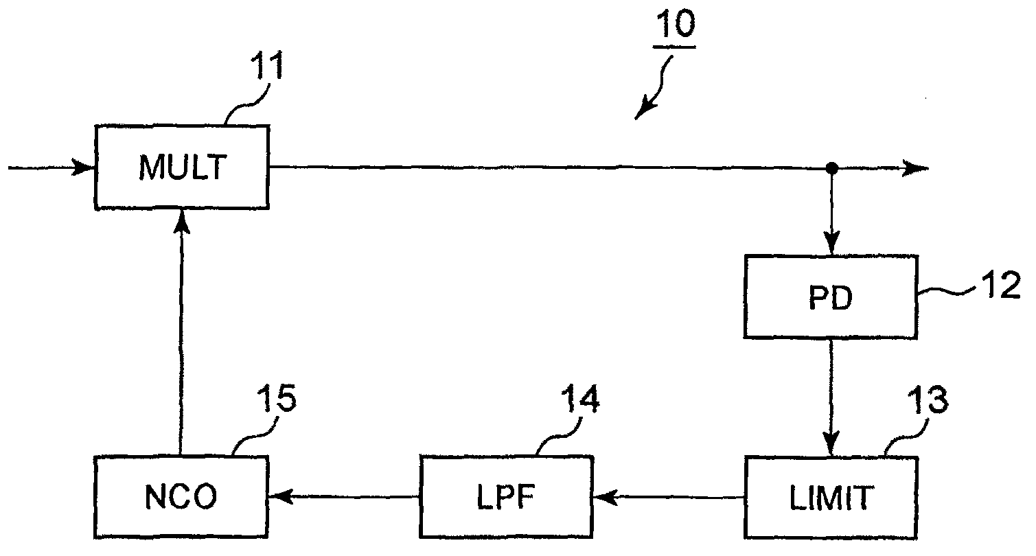
[0035] For easy understanding of the present invention, the prior art and its problems are first described in detail. Note that the prior art mentioned here is the most basic PLL circuit known. This is because there is no other known technique effective for both carrier recovery and clock synchronization other than the most basic PLL circuit.

[0036] As described above, in carrier recovery and clock synchronization, which are the main signal processing performed in the demodulator, information to be extracted is not explicitly sent from the transmission side. Therefore, it is necessary to restore the carrier and the clock signal based on the result of demodulating the received signal, and synchronize the restored carrier with the frequency and phase of the transmission side. Thus, BER characteristics at the time of demodulation affect the control, or noise superimposed on the constellation points affects the control.

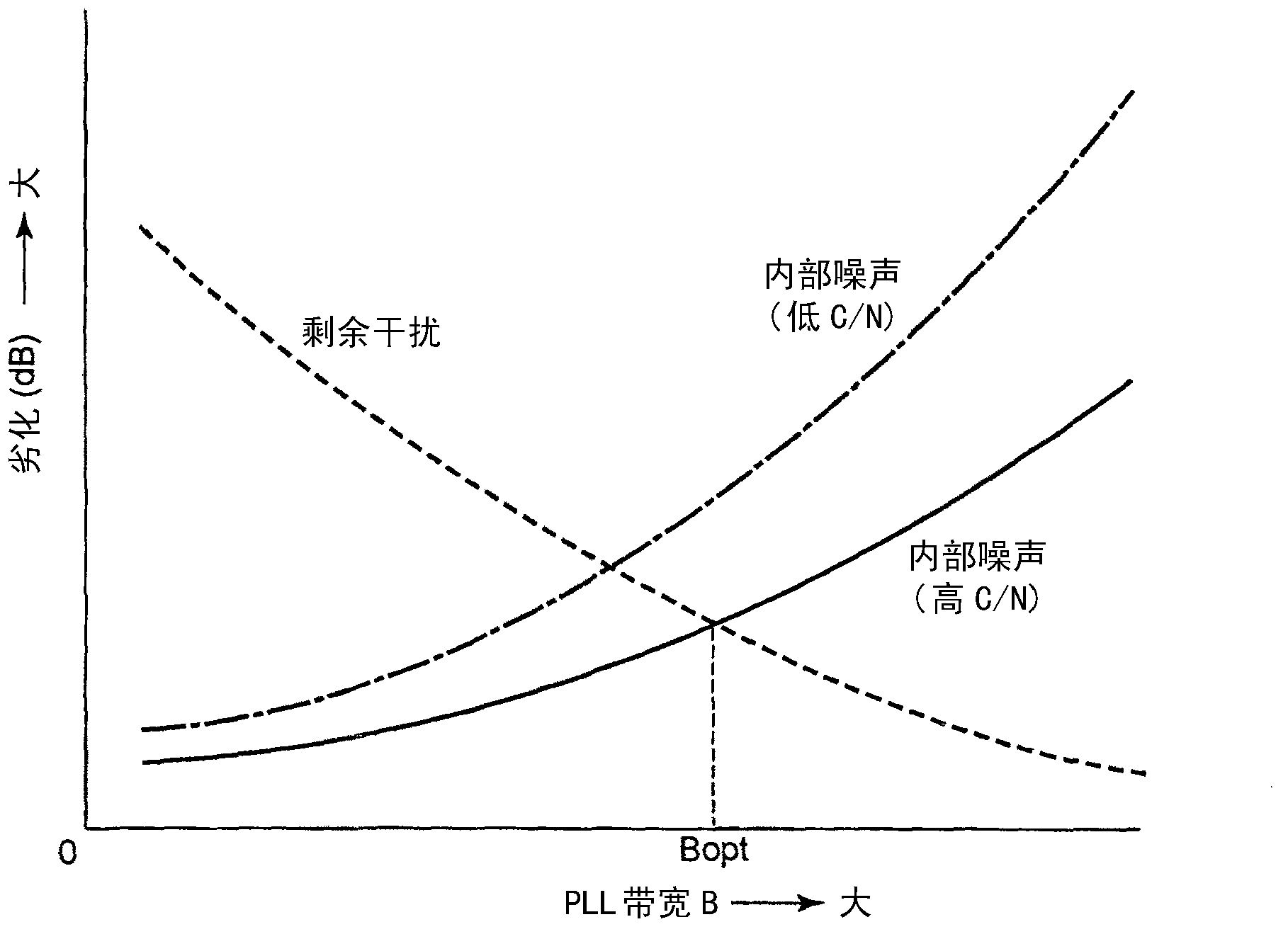
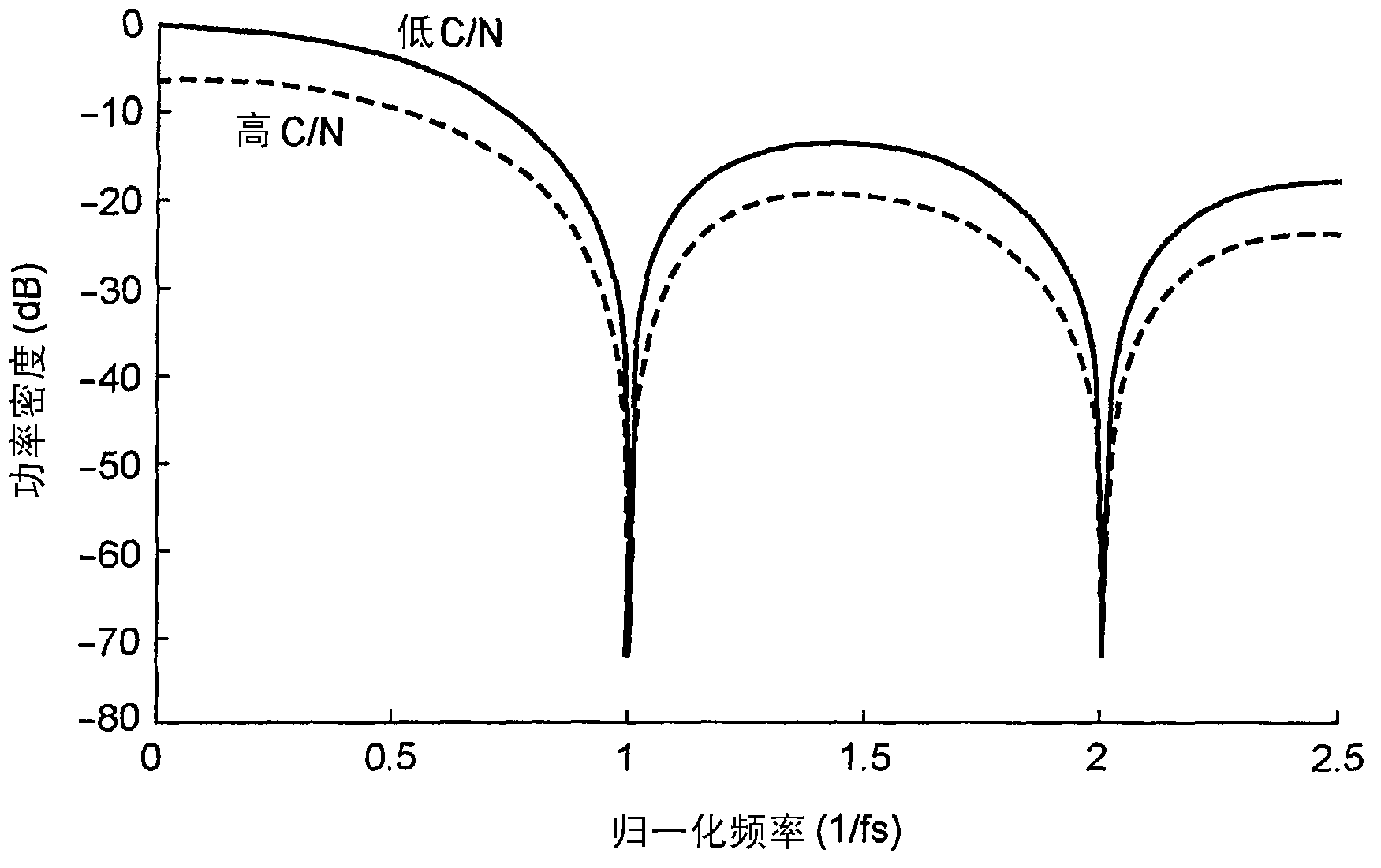
[0037] The influence is described below.

[0038] refe...


PUM


Abstract

A PLL circuit of the present invention, which extracts phase error information from a demodulated signal in which the variance of the phase or the amplitude changes depending upon the signal-to-noise ratio and suppresses the phase error of the demodulated signal by applying negative feedback control thereto, includes a phase detector for outputting, as phase error information, a phase error signal corresponding to the value of the phase error, a limiter circuit for limiting expression ranges of the phase error signal to a constant value or below so as to output the phase error signal to which the limit has been applied, and a loop filter which outputs a control signal on the basis of the phase error signal to which the limit has been applied so as to determine the frequency characteristics thereof.

Description

technical field [0001] The present invention relates to a digital wireless system, and more particularly, to a PLL circuit for a multilevel quadrature amplitude modulation (QAM) demodulator. Background technique [0002] In recent years, in digital wireless systems for millimeter waves or microwaves whose demand is rapidly increasing as components in mobile communication systems, multi-level quadrature amplitudes capable of high-capacity transmission and easy digitization of modulator / demodulator circuits A modulation (QAM) scheme is used as the modulation scheme. [0003] An RF local oscillator (LO) signal used for frequency conversion between an intermediate frequency (IF) signal and a radio frequency (RF) signal has phase noise. In general, the phase noise level (expressed as the power density ratio of the power density at frequencies away from the center frequency (e.g., 100 kHz offset) to the power density at the center frequency) gets higher as the frequency of the LO...

Claims


Application Information

Patent Timeline
Patent Type & Authority Applications(China)
IPC IPC(8): H04L27/38H03L7/08H03L7/093
CPCH03L7/0807H04L27/0014H04L27/38H04L2027/0067H03L7/091H03L7/08
Inventor 佐佐木英作
Owner NEC CORP
Why Eureka
Try Eureka