Band limiting method and wireless communication system
a wireless communication system and band limit technology, applied in the field of band limit method, can solve the problems of short reaching distance of transmission signal and narrow communication range, and achieve the effects of reducing papr, improving communication range, and high frequency use efficiency
- Summary
- Abstract
- Description
- Claims
- Application Information
AI Technical Summary
Benefits of technology
Problems solved by technology
Method used
Image
Examples
first exemplary embodiment
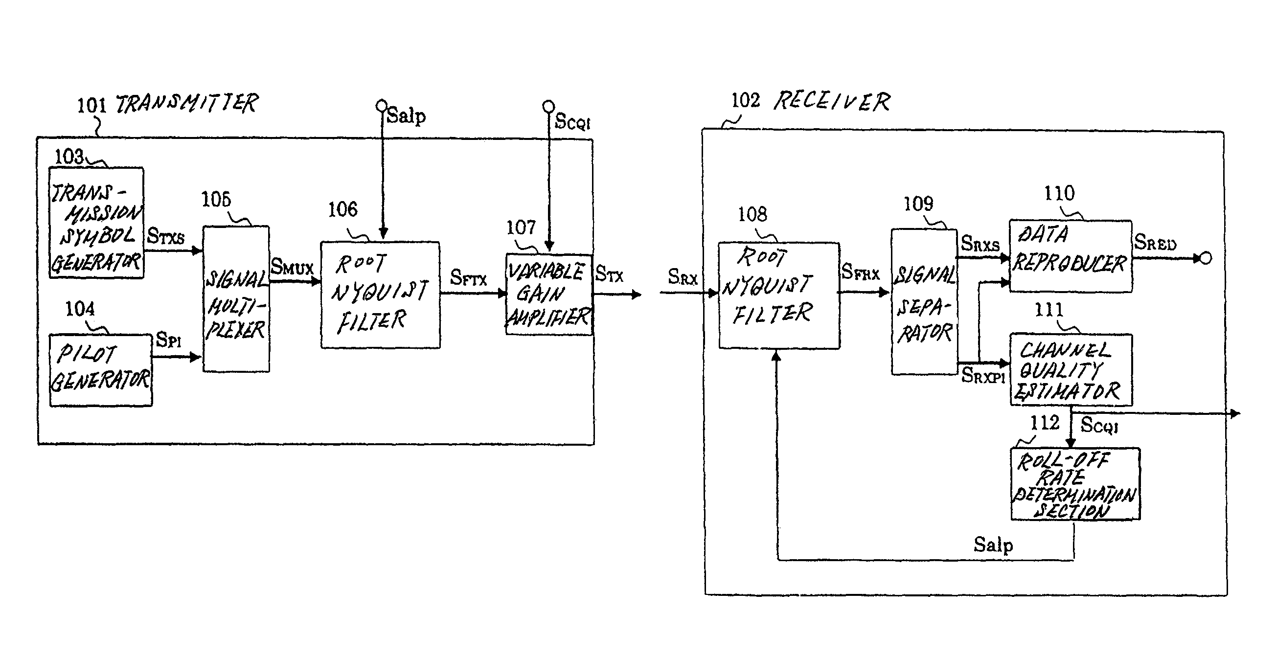
[0026]FIG. 3 is a block diagram showing a configuration of a first exemplary embodiment of a wireless communication system of the present invention.
[0027]As shown in FIG. 3, the wireless communication system of the first exemplary embodiment comprises transmitter 101 and receiver 102.
[0028]Transmitter 101 comprises transmission symbol generator 103, pilot generator 104, signal multiplexer 105, root Nyquist filter 106, and variable gain amplifier 107.
[0029]Transmission symbol generator 103 generates transmission information to perform symbol mapping and outputs transmission symbol sequence STXS. Pilot generator 104 generates pilot symbol SPI. Signal multiplexer 105 multiplexes transmission symbol sequence STXS and pilot symbol SPI and outputs multiplexed signal SMUX. Root Nyquist filter 106 applies filtering with root roll-off characteristics corresponding to roll-off rate information Salp to multiplexed signal SMUX and outputs filtering transmission signal SFTX. Variable gain amplif...
second exemplary embodiment
[0047]FIG. 5 is a block diagram showing a configuration of a second exemplary embodiment of the Wireless communication system of the present invention.
[0048]As shown in FIG. 5, the wireless communication system of the second exemplary embodiment comprises transmitter 201 and receiver 202.
[0049]Transmitter 201 comprises transmission symbol generator 103, pilot generator 104, signal multiplexer 105, root Nyquist filter 106, variable gain amplifier 107, and roll-off rate determination section 203.
[0050]Transmission symbol generator 103 generates transmission information to perform symbol mapping and outputs transmission symbol sequence STXS. Pilot generator 104 generates pilot symbol SPI. Signal multiplexer 105 multiplexes transmission symbol sequence STXS and pilot symbol SPI and outputs multiplexed signal SMUX. Roll-off rate determination section 203 determines a roll-off rate from channel quality information SCQI and outputs roll-off rate information Salp. Root Nyquist filter 106 ap...
third exemplary embodiment
[0061]FIG. 6 is a block diagram showing a configuration of a third exemplary embodiment of the wireless communication system of the present invention.
[0062]As shown in FIG. 6, the wireless communication system of the third exemplary embodiment comprises transmitter 301 and receiver 302.
[0063]Transmitter 301 comprises transmission symbol generator 103, pilot generator 104, signal multiplexer 105, root Nyquist filter 106, variable gain amplifier 107, frequency resource selector 303, and frequency shifter 304.
[0064]Transmission symbol generator 103 generates transmission information to perform symbol mapping and outputs transmission symbol sequence STXS. Pilot generator 104 generates pilot symbol SPI. Signal multiplexer 105 multiplexes transmission symbol sequence STXS and pilot symbol SPI and outputs multiplexed signal SMUX. Root Nyquist filter 106 applies filtering with root roll-off characteristics corresponding to roll-off rate information Salp to multiplexed signal SMUX and output...
PUM
 Abstract
Description
Claims
Application Information
 - R&D
- Intellectual Property
- Life Sciences
- Materials
- Tech Scout
- Unparalleled Data Quality
- Higher Quality Content
- 60% Fewer Hallucinations
Browse by: Latest US Patents, China's latest patents, Technical Efficacy Thesaurus, Application Domain, Technology Topic, Popular Technical Reports.
© 2025 PatSnap. All rights reserved.Legal|Privacy policy|Modern Slavery Act Transparency Statement|Sitemap|About US| Contact US: help@patsnap.com


