OFDM signal receiver device and OFDM signal receiving method

a receiver device and signal technology, applied in the direction of synchronising signal speed/phase control, code conversion, coding, etc., can solve the problem that the error rate corresponding to the signal after demodulating the demodulated signal cannot be sufficiently small, and the average noise power or signal-to-noise power ratio also varies over time, so as to reduce the adverse effects of change over tim

Inactive Publication Date: 2009-09-01
MITSUBISHI ELECTRIC CORP
View PDF7 Cites 3 Cited by
  • Summary
  • Abstract
  • Description
  • Claims
  • Application Information

AI Technical Summary

Benefits of technology

[0007]The present invention has been accomplished to resolve such a problem as described above, and its object is to obtain an OFDM signal receiver device that can lessen adverse effects from change over time in the average noise power or the signal-to-noise power ratio or from their absolute values by weighting branch metrics based on the average noise power or the signal-to-noise power ratio and performing Viterbi decoding based on the results of the weighting.
[0009]The embodiment of the OFDM signal receiver device according to the present invention makes possible Viterbi decoding taking noise power into account and can reduce error rate after decoding.

Problems solved by technology

Nevertheless, when receiving OFDM signal while in transit, the power of received signal changes greatly over time, and therefore, the average noise power or the signal-to-noise power ratio also varies over time.
However, the Euclidean distance that is calculated from demodulated signal does not take into account the absolute amount of the average noise power contained in the demodulated signal or the signal-to-noise power ratio; thus, there has been a problem that the adverse effect caused by the power corresponding to the noise cannot be suppressed in decoding the demodulated signal and the error rate corresponding to the signal after decoding the demodulated signal cannot be made sufficiently small.

Method used


Image

  • OFDM signal receiver device and OFDM signal receiving method
  • OFDM signal receiver device and OFDM signal receiving method
  • OFDM signal receiver device and OFDM signal receiving method

Examples


first preferred embodiment

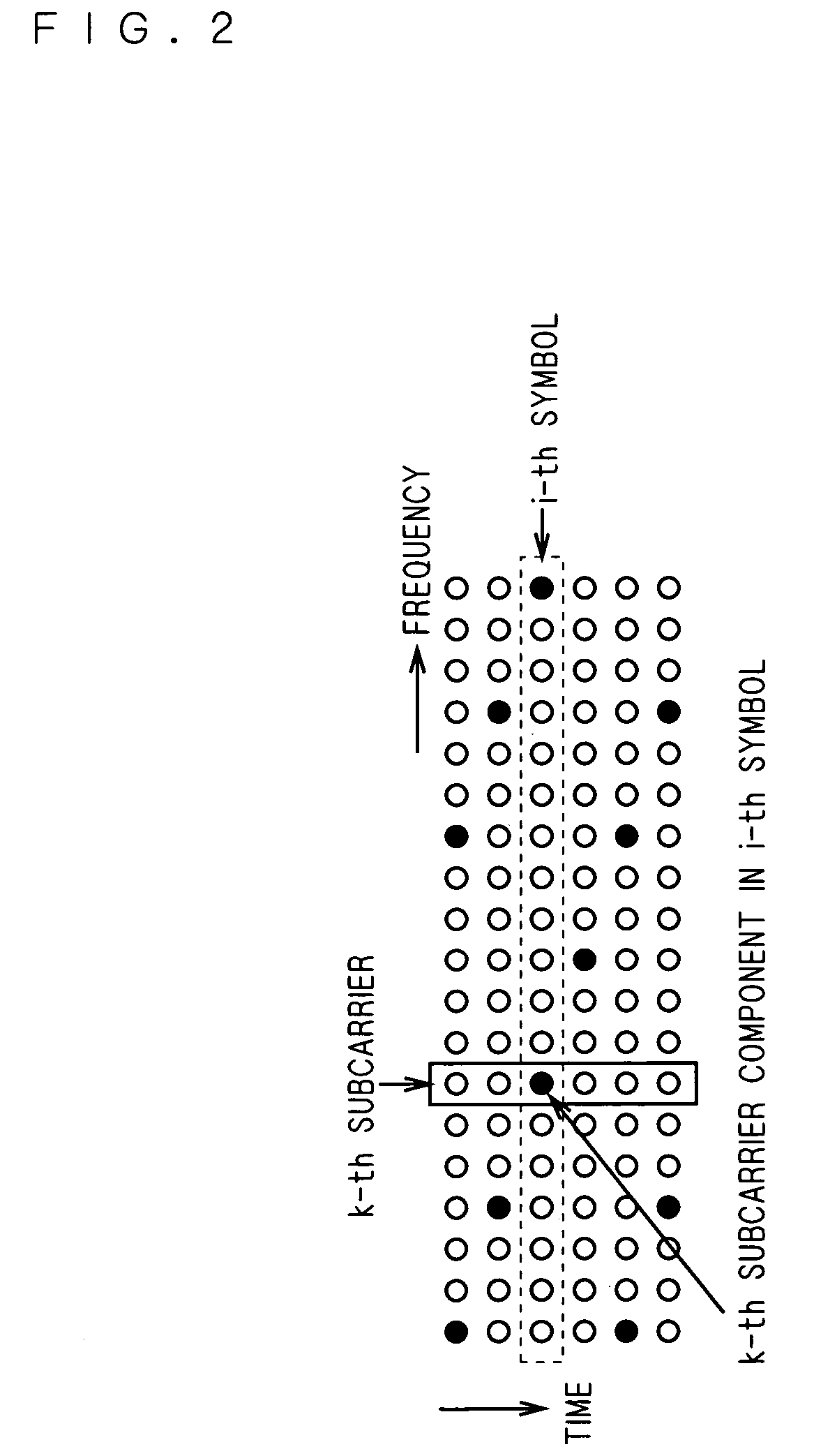
[0023]First, the transmission technology of orthogonal frequency division multiplexing system is explained. The orthogonal frequency division multiplexing system is a transmission system that uses a plurality of carrier waves (hereinafter also referred to as “subcarrier components”) the frequencies of which are orthogonal to each other to transmit transmission data, and the transmission data are reproduced with a receiver device. This first preferred embodiment explains a case in which convolutionally coded transmission data are transmitted and received according to the orthogonal frequency division multiplexing format. In this case, in a transmission device, transmission data that are convolutionally coded at a predetermined coding rate are assigned a signal constellation according to the modulation format of each subcarrier component. Specifically, the transmission data are subjected to an inverse Fourier transform to generate a signal in which a plurality of subcarrier components...

second preferred embodiment

[0038]The receiver device in the first preferred embodiment generates a noise power signal based on a demodulated pilot signal, and calculates a weighting factor for a branch metric based on the resultant noise power signal. A receiver device in the present preferred embodiment generates a noise power signal from an input level of a received signal, and calculates a weighting factor for a branch metric based on the resultant noise power signal.

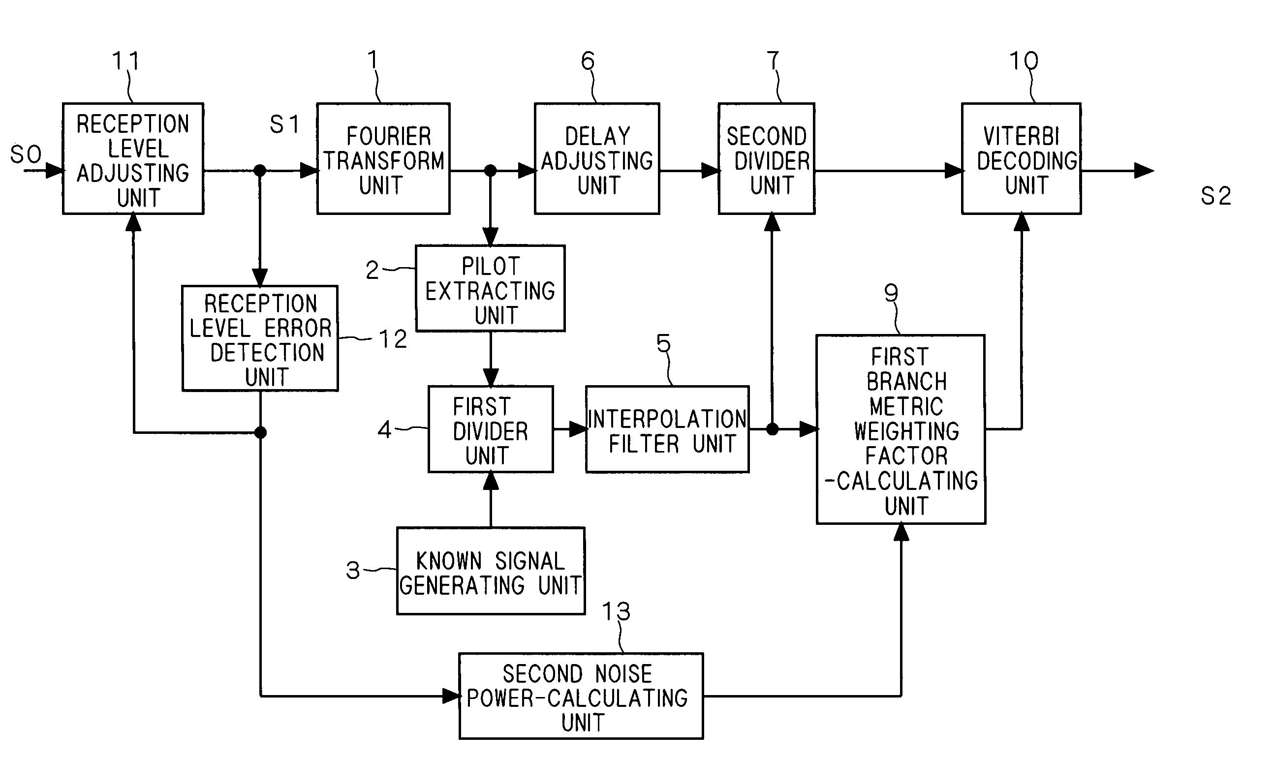
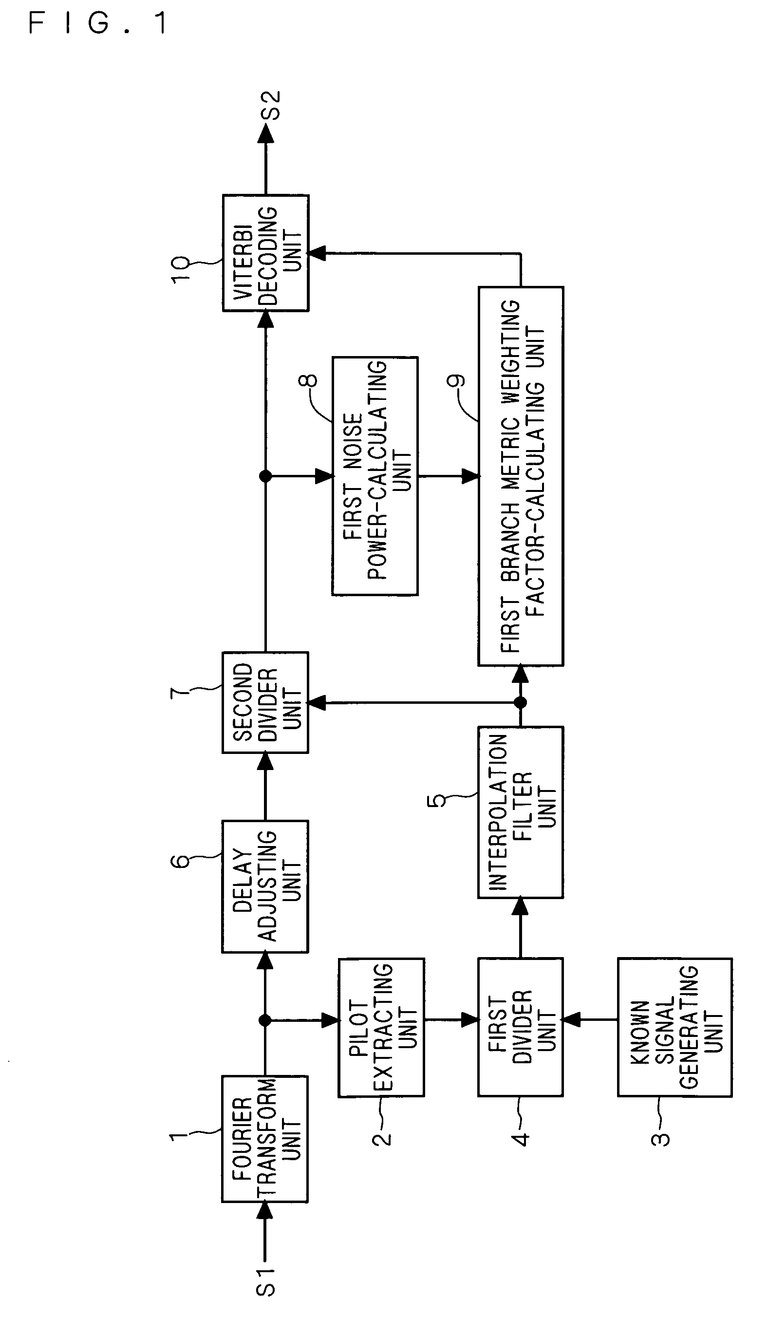
[0039]FIG. 7 shows a configuration diagram of the receiver device according to the present preferred embodiment. The receiver device shown in FIG. 7 employs: a Fourier transform unit 1, a pilot extracting unit 2, a known signal generating unit 3, a first divider unit 4, an interpolation filter unit 5, a delay adjusting unit 6, a second divider unit 7, a first branch metric weighting factor-calculating unit 9, and a Viterbi decoding unit 10; and these components have the same functions as those in the first preferred embodiment. For that reason...

third preferred embodiment

[0044]The receiver device in the first preferred embodiment calculates a weighting factor for a branch metric by calculating the transmission channel characteristic power information of each subcarrier component from the output of the interpolation filter 5 with the first branch metric weighting factor-calculating unit 9, multiplying this transmission channel characteristic power information by a coefficient according to a noise power signal, and further adding an offset value thereto. The receiver device in present preferred embodiment calculates a weighting factor for a branch metric by performing a signal conversion on the transmission channel characteristic power information using a predetermined function, multiplying the signal that has undergone the conversion by a coefficient according to a noise power signal, and further adding an offset value thereto.

[0045]FIG. 8 shows a configuration diagram of the receiver device according to the present preferred embodiment. The receiver...


PUM


Abstract

The present invention relates to a OFDM signal receiver device that performs weighting for branch metrics based on average noise power or signal-to-noise power ratio and conducts Viterbi decoding based on the result of the weighting. In the present invention, based on a demodulated signal, electric power corresponding to a noise component contained in the demodulated signal is calculated. A noise power signal corresponding to the result of the calculation is output from a noise power-calculating unit 8. Based on the noise power signal and a transmission channel characteristic corresponding to a subcarrier component that is output from an interpolation filter unit, a weighing factor for a branch metric is calculated by a weighting factor-calculating unit 9, and based on the weighting factor, the demodulated signal is decoded by decoding unit 10.

Description

TECHNICAL FIELD[0001]The present invention relates to a receiver device and a method of receiving orthogonal frequency division multiplexing (hereinafter referred to as “OFDM”) signal.BACKGROUND ART[0002]A conventional OFDM signal receiver device (hereinafter also simply referred to as a “receiver device”) performs a Fourier transform on an OFDM signal. Then, in synchronization with a subcarrier component obtained as a result of the Fourier transform, the receiver device generates a pre-transmission pilot signal (hereinafter also referred to as a “transmission pilot signal”), which is a known signal. By dividing a subcarrier component of a pilot signal in the subcarrier component contained in a received OFDM signal (hereinafter the pilot signal is also referred to as a “received pilot signal”) by the transmission pilot signal, the receiver device calculates transmission channel characteristic corresponding to the received pilot signal. Then, by filtering the transmission channel cha...

Claims


Application Information

Patent Timeline
Patent Type & Authority Patents(United States)
IPC IPC(8): H04K1/10H04J11/00H04L27/26
CPCH03M13/4107H03M13/658H04L1/0047H04L27/2647H04L1/0054H04L25/0232H04L25/03159
Inventor IDO, JUNARITA, EIJI
Owner MITSUBISHI ELECTRIC CORP
Why Eureka
Try Eureka