Electrohydraulic controlled continuously variable gas distribution timing system in internal-combustion engine

An electro-hydraulic control and timing system technology, which is applied in mechanical equipment, engine components, machines/engines, etc., can solve the problems of not being able to meet low fuel consumption, and cannot realize continuous variable gas distribution timing, so as to improve fuel economy and increase Dynamic performance, the effect of improving dynamic performance

Inactive Publication Date: 2007-05-09
济南轻骑摩托车有限公司 +1
View PDF0 Cites 25 Cited by
  • Summary
  • Abstract
  • Description
  • Claims
  • Application Information

AI Technical Summary

Problems solved by technology

However, these mechanisms cannot achieve continuous variable valve timing, so they cannot meet the requirements

Method used


Image

  • Electrohydraulic controlled continuously variable gas distribution timing system in internal-combustion engine
  • Electrohydraulic controlled continuously variable gas distribution timing system in internal-combustion engine

Examples


Embodiment Construction

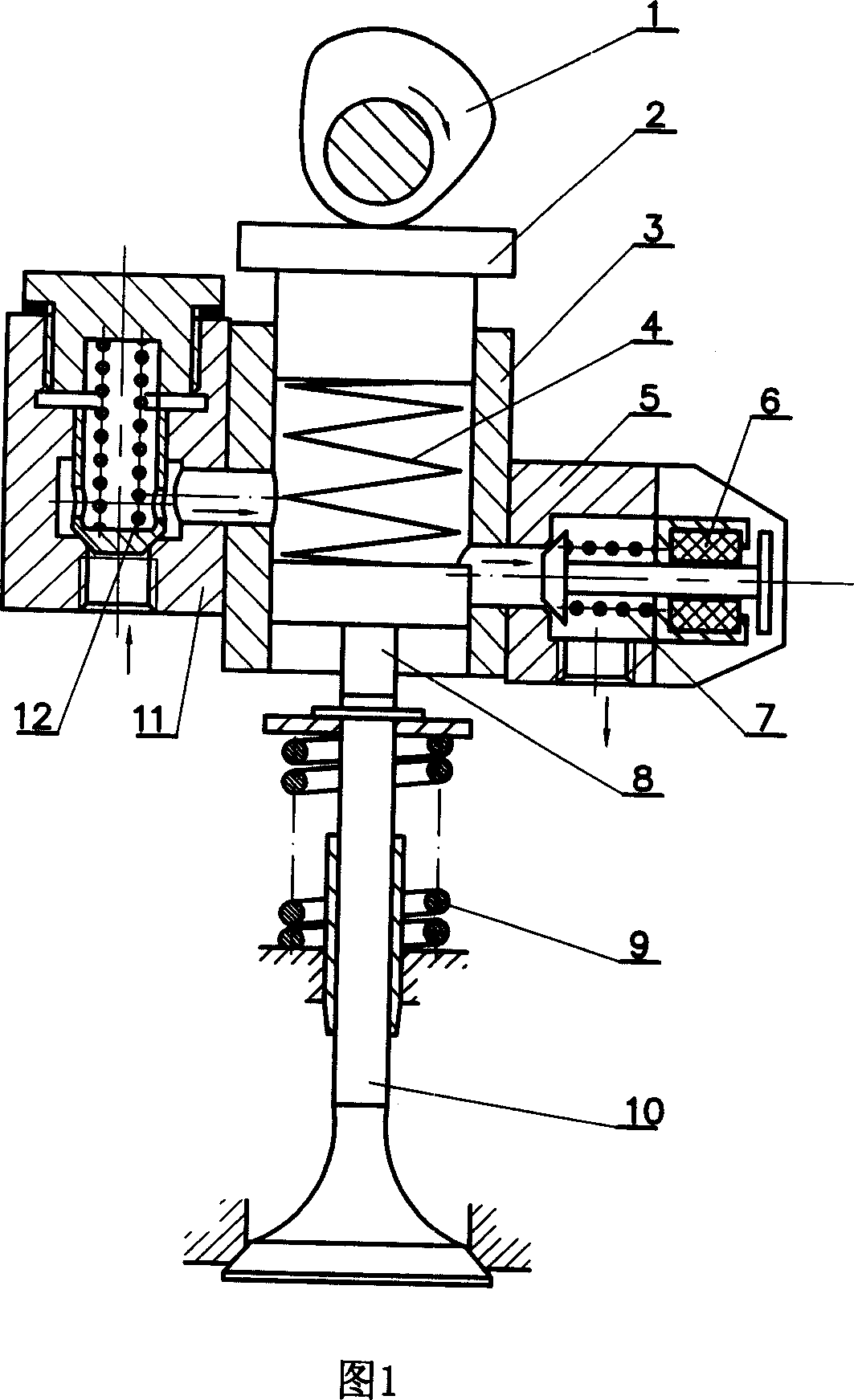
[0018] The working process of the present invention will be described in detail below in conjunction with the accompanying drawings. In Fig. 1, the left side is the inlet check valve part, including the check valve body 11, the check valve spring 12, etc.; the right side is the one-way electromagnetic booster valve part, including the solenoid valve body 5, the solenoid coil 6 and The valve spring 7, etc.; the middle part is the valve driving mechanism, including the gas distribution cam 1, the tappet 2, the tappet return spring 4, the hydraulic cylinder block 3, the hydraulic piston 8, the valve spring 9 and the valve 10, etc. The gas distribution cam 1 in the camshaft transmission assembly drives the tappet 2, and the tappet 2 is placed in the hydraulic cylinder body 3 so that it can move axially, and part of the outer circular surface of the tappet 2 is sealed with one end of the inner wall of the hydraulic cylinder. 3 The other end of the inner wall is a hydraulic piston 8...


PUM


Abstract

A continuous variable valve actuating-timing system controlled by electrohydraulic control and set on internal combustion engine is prepared as using entrance one-way valve to control oil intake of hydraulic cylinder and using one-way solenoid valve to control oil exhaust of hydraulic cylinder, using rise-up section of valve actuating cam to control open and rise-up of air door and controlling close and drop-down of air door by depending upon exhausting time of liquid in hydraulic cylinder.

Description

technical field [0001] The invention relates to the technical field of internal combustion engines, in particular to a gas distribution system of an ignition type internal combustion engine. Background technique [0002] Ignition internal combustion engine load adjustment is achieved by changing the amount of combustible mixture entering the cylinder, that is, changing the amount of combustible mixture entering the cylinder by adjusting the throttle opening. When the speed of the internal combustion engine remains constant, the opening of the throttle valve increases, the amount of combustible mixture entering the cylinder increases, and the output power of the internal combustion engine increases accordingly; otherwise, it decreases. When the internal combustion engine works under small and medium load conditions, due to the small opening of the throttle valve, the pumping loss of the internal combustion engine will increase significantly, which will eventually lead to an i...

Claims


Application Information

Patent Timeline
IPC IPC(8): F01L9/02F01L9/11
Inventor 谢宗法曹心诚冯延勇
Owner 济南轻骑摩托车有限公司
Why Eureka
Try Eureka