
Wheel and mechanical leg joint multiplexing motor transmission system and driving method

A technology of motor transmission and driving method, which is applied in the direction of motor vehicles, power devices, motion deposition, etc., can solve the problems of low transmission efficiency, large space occupation, and complex structure of mechanical legs, and achieve agile action, high energy density, and large output The effect of torque

Active Publication Date: 2020-11-24
NORTHEAST FORESTRY UNIVERSITY
View PDF10 Cites 0 Cited by
  • Summary
  • Abstract
  • Description
  • Claims
  • Application Information

AI Technical Summary

Problems solved by technology

[0004] In view of the above analysis, the present invention aims to provide a wheel and mechanical leg joint multiplexed motor drive system and driving method to solve the problems of existing mechanical legs with complex structure, low transmission efficiency and large space occupation

Method used


Image

  • Wheel and mechanical leg joint multiplexing motor transmission system and driving method

Examples


Embodiment 1

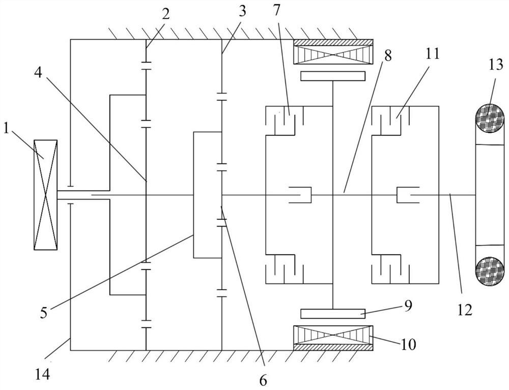
[0038] Such as figure 1 As shown, the embodiment of the present invention provides a wheel and mechanical leg joint multiplexing motor transmission system, the wheel and mechanical leg joint multiplexing motor transmission system includes: a first clutch 11, a second clutch 7, a planetary gear set reducer, Wheel 13 and hub motor; the hub motor is installed in the mechanical leg housing 14, and the planetary gear set reducer ring gear is installed in the mechanical leg housing 14; the output shaft 8 of the hub motor is connected to the input end of the first clutch 11 and the second clutch at the same time 7; the output end of the first clutch 11 is connected to the wheel 13; the output end of the second clutch 7 is connected to the input end of the planetary gear set reducer; the output end of the planetary gear set reducer is connected to the leg joint 1.

[0039] When the first clutch 11 is connected and the second clutch 7 is disconnected, in the embodiment of the present i...

Embodiment 2

[0051] An embodiment of the present invention provides a driving method for multiplexing a wheel and a mechanical leg joint. The embodiment of the present invention uses the multiplexing motor transmission system for a wheel and a mechanical leg joint in Embodiment 1.

[0052] The driving method in the embodiment of the present invention includes wheel driving and step driving. When using wheel drive, the wheel-step platform uses the transmission system in Embodiment 1 to move wheel-type, that is, the wheel hub motor finally drives the wheel 13 to rotate, so that the wheel-step platform moves in the form of a car through the rotation of the wheel 13. When using step-type drive, the wheel-step platform uses the transmission system in Embodiment 1 to move step-by-step, that is, the hub motor finally makes the transmission system rotate as a mechanical leg, so that the wheel-step platform moves by turning the mechanical leg and taking steps. Two kinds of driving methods can not b...


PUM


Abstract

The invention relates to a wheel and mechanical leg joint multiplexing motor transmission system and a driving method, belongs to the technical field of wheel and walking robots, and solves the problems of complex structure, low transmission efficiency and large occupied space of an existing mechanical leg. The transmission system comprises a first clutch, a second clutch, a planetary gear set reducer, wheels and a hub motor, wherein the hub motor is arranged in a mechanical leg shell, and a gear ring of the planetary gear set reducer is arranged in the mechanical leg shell; an output shaft ofthe hub motor is simultaneously connected with the input end of the first clutch and the input end of the second clutch; the output end of the first clutch is connected with the wheels; the output end of the second clutch is connected with the input end of the planetary gear set reducer; and the output end of the planetary gear set reducer is connected with a leg joint. The wheel and mechanical leg joint multiplexing motor transmission system and the driving method can cope with changeable and complex road conditions and realize an efficient compact type composite driving system which can beused for driving through both the wheels and legs.

Description

technical field [0001] The invention relates to the technical field of wheel-step robots, in particular to a wheel and mechanical leg joint multiplexing motor transmission system and a driving method. Background technique [0002] In a complex terrain environment, it is a challenging task to efficiently and quickly transport personnel, supplies and equipment to their destinations. In order to meet the needs of goods transportation in areas where regular roads cannot be built due to technical or other reasons, and to improve the efficiency of transportation, it is necessary to design wheel-step robots to transport necessities in small-scale emergency situations. [0003] This kind of robot uses wheel drive in the environment with regularized roads. The characteristics of this maneuvering mode are fast maneuvering and high speed. When the environment does not have regular roads and ordinary vehicles cannot pass through, the motorized platform is required to maneuver through l...

Claims


Application Information

Patent Timeline
Patent Type & Authority Applications(China)
IPC IPC(8): B62D57/028B60K7/00B60K17/04B60K17/02
CPCB62D57/028B60K7/0007B60K17/04B60K17/02B60K2007/0092B60K2007/0038
Inventor 李麟金子微席军强李鑫
Owner NORTHEAST FORESTRY UNIVERSITY
Learn More