
Hybrid window wall/curtain wall system and method of installation

Active Publication Date: 2006-01-26
SOTAWALL LTD
View PDF44 Cites 36 Cited by
  • Summary
  • Abstract
  • Description
  • Claims
  • Application Information

AI Technical Summary

Benefits of technology

[0020] It is therefore an object of the invention to provide an improved window or curtain wall system and method of installation for such a system, which obviates or mitigates at least one of the disadvantages described above.
[0023] The invention provides a building envelope system that has the performance of a curtain wall system, but uses rigid panels that are installed between floors. This results in a high performance installation at a lower labour cost, with easier installation of sound and fire sealing.

Problems solved by technology

The exterior shell provides an insulating, weather-proof, generally air-tight and aesthetic cladding, but essentially no structural strength.
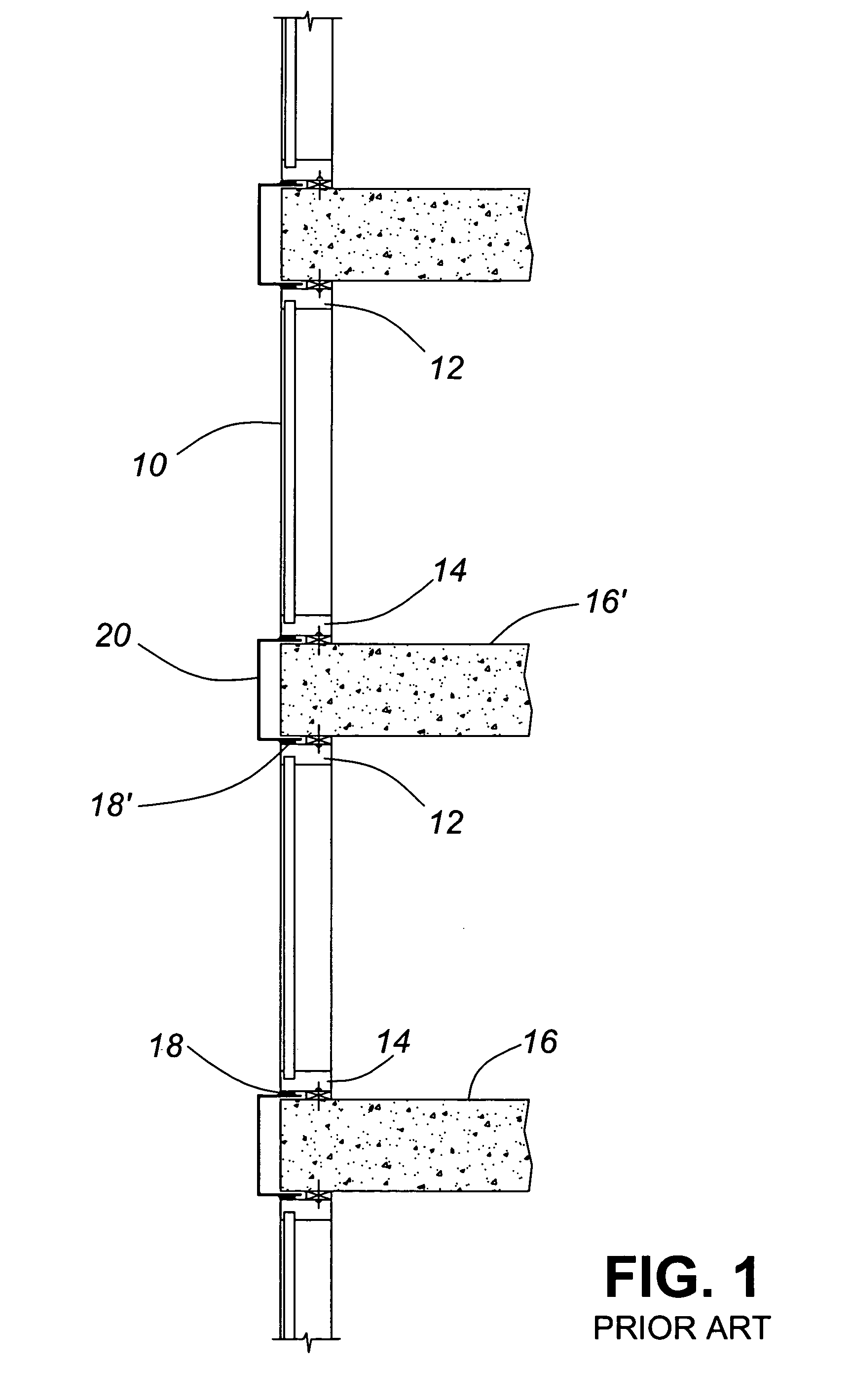
Window wall systems suffer from a number of problems the most significant of which is poor long-term performance.
As noted above, regular window wall are sealed with caulking between the rigid panels and the floor slabs—eventually this caulking is going to break down and leakage will occur.
This cycling keeps compressing and decompressing the rigid frames repeatedly, placing a strain on the caulking until it begins to break down.
The length of time that it takes for this breakdown to occur depends on the environment and the specifics of the installation, but these components often start opening up after two to five years, thus requiring maintenance.
Once the caulking joints start opening up, water will get into the system and damage both the window wall system and the building interior.
This deterioration and long-term performance is a severe problem with window wall systems.
Of course, the caulking must also be installed properly in the first place, which is not an easy task.
Even pinholes or small cracks may allow water to leak into the building, particularly on the windward side of the building which experiences significant levels of air pressure across the cladding system.
If too thin a layer of caulking is applied, or if the surfaces are dirty, oily or wet when the caulking is applied, the seal may fail very quickly or be ineffective right from the beginning.
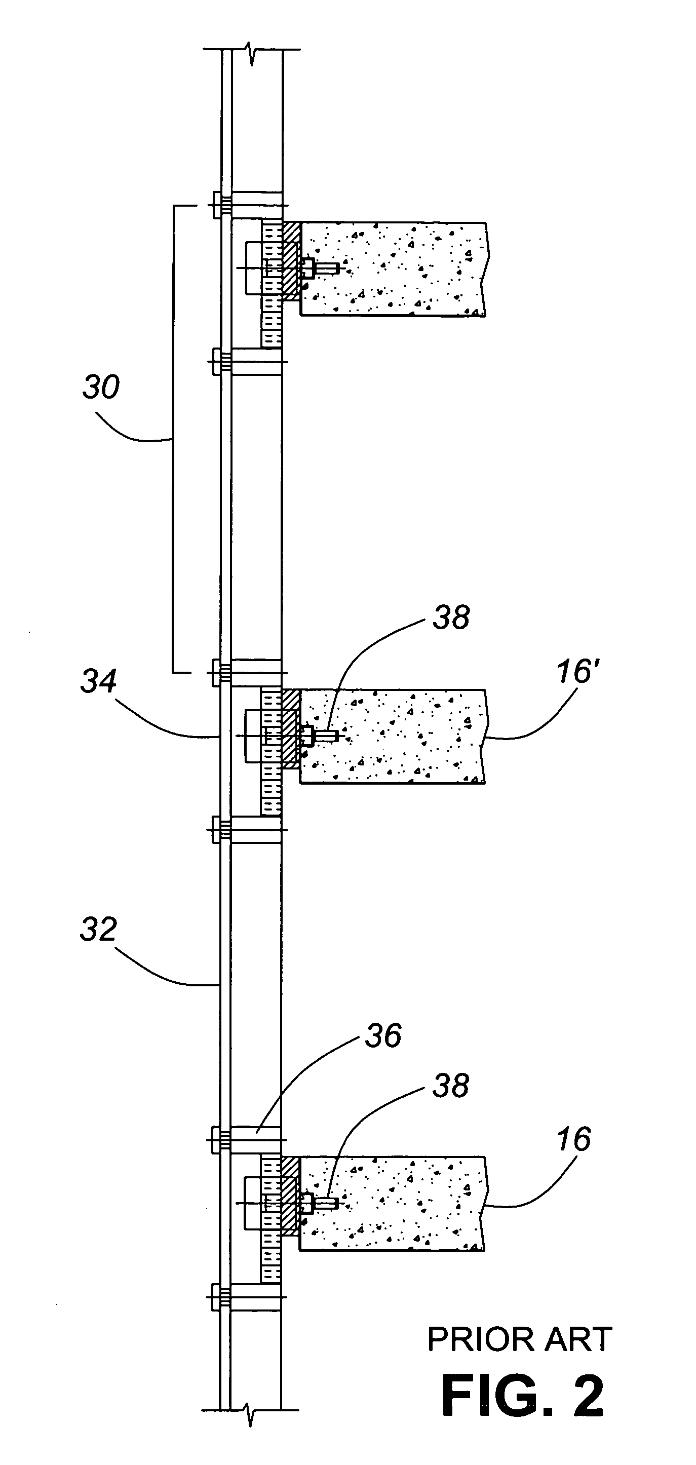
Conventional curtain wall systems generally do not have the caulking / leakage problem of window wall systems, but they have problems of their own.
While these issues can be addressed with suitable sealing systems, the larger the gaps are, the more expensive and time consuming they are to fill and they result in a possible failure point for the system.
A related problem is that conventional curtain wall systems have vertical mullions which run continuously from the bottom to the top of the building.
The interiors of these vertical mullions are not sealed between floors and it would be very expensive and inconvenient to do so.
The supply, layout and installation of these embedded anchors 38 is a costly item, particularly in high labor cost markets.
Expansion anchors and other types of concrete fasteners simply are not strong enough to support such loads reliably.
This allows for some vertical movement, but the interface of the rigid panel and the horizontal channel still has to be caulked, so it will eventually break down; and this additional interface introduces another point for possible air and water leakage.
None of these modified window wall or curtain wall systems have been very successful.
The uniform response from developers and architects was that they are tired of the poor long-term performance of window wall systems and of the standard “prison look” effect due to restrictions in module width and wide mullion assemblies.
Also, the appearance of slab-edge metal cover panels 20 was not aesthetically pleasing.
Installers are expensive, especially in markets where the cost of living is high, such as in Manhatten, N.Y. Because of the high labour costs and low productivity levels in such environments, it is also desirable to employ as much factory pre-fabrication as possible.

Method used


Image

  • Hybrid window wall/curtain wall system and method of installation
  • Hybrid window wall/curtain wall system and method of installation
  • Hybrid window wall/curtain wall system and method of installation

Examples


Embodiment Construction

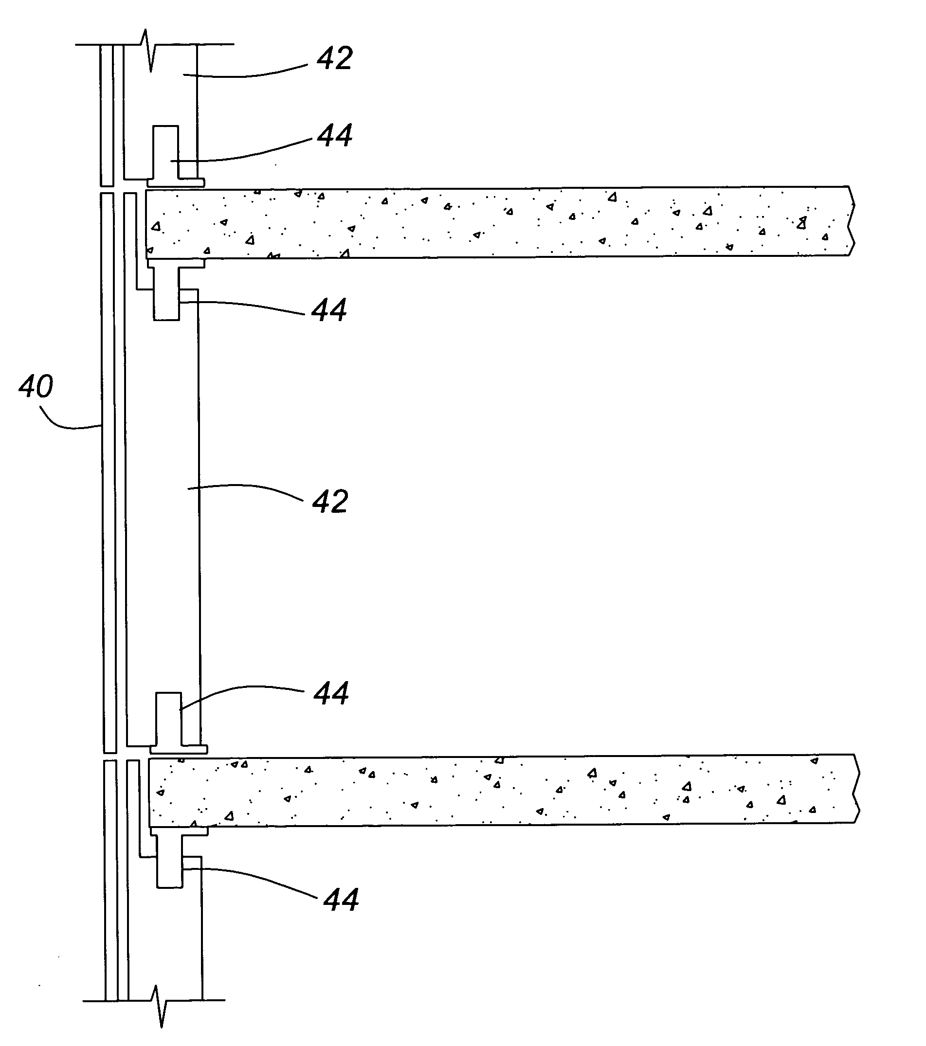
[0036] The invention adapts and modifies a conventional unitized curtain wall system so that it can be installed between concrete floor slabs similar to a conventional window wall system. Modifications were made without negative impact to the superior performance, appearance options and installation capabilities of a conventional unitized curtain wall system.

[0037] The main problems of the known systems were solved by notching a conventional unitized curtain wall systems (Sota Glazing's Millennium Series and Thermo 3 Series were used in the development of the invention) around the concrete floor slabs without interrupting the continuous integral gasketed, airseal system of the curtain wall system. A conventional window wall system is completely interrupted between concrete floor slabs and relies on caulked joints between window frames and the concrete floor slabs to create a continuous airseal barrier.

[0038] The notching of the curtain wall system around the concrete floor slabs a...


PUM


Abstract

There are currently two major types of exterior building envelope finishing systems: window wall systems, and curtain wall systems. Window wall systems use panels which fit between concrete floor slaps, and hence, are prone to leakage and are not aesthetically appealing. Curtain wall systems are installed proud of the concrete slabs, so have better performance, but are expensive to install. The system of the invention has the high performance of a curtain wall system, with the ease of installation of a window wall system. The invention uses rigid panels which cover the face of a building like a curtain wall system, providing a complete gasketed seal without the need for caulking as in the case of window wall systems. The vertical mullions are notched, so that the mullions can be easily anchored to the upper and lower surfaces of the concrete slabs.

Description

FIELD OF INVENTION [0001] The present invention relates generally to exterior building envelope finishing systems, and more particularly to improvements over curtain wall and window wall systems and the like. BACKGROUND OF THE INVENTION [0002] The current approach to the construction of large highrise commercial or residential buildings is to first construct a self-supporting structure of a roof, floors and interior bearing members (including posts, beams, bearing walls, columns, and other structural supports), generally out of concrete and / or steel, and then to encase this structure with an exterior shell. The exterior shell provides an insulating, weather-proof, generally air-tight and aesthetic cladding, but essentially no structural strength. The two most common types of exterior shell systems for such buildings are called “window wall” systems and “curtain wall” systems. [0003] In window wall systems, rigid panels of a manageable size and weight are prefabricated to roughly the...

Claims


Application Information

Patent Timeline
IPC IPC(8): E04H6/00
CPCE04B2/96E04B2/90E04B1/94E04B2001/7679
Inventor SPECK, JUAN ANTONIO
Owner SOTAWALL LTD
Learn More