Valve position controlller

a position controller and valve technology, applied in the direction of engine controllers, electric control, machines/engines, etc., can solve the problems of increasing the number of parts and increasing the cost, and achieve the effect of decreasing the number of parts and the cos

Inactive Publication Date: 2006-01-26
DENSO CORP
View PDF6 Cites 63 Cited by
  • Summary
  • Abstract
  • Description
  • Claims
  • Application Information

AI Technical Summary

Benefits of technology

[0006] It is an object of the present invention to provide a valve position controller which is capable of decreasing the number of parts and the cost by using the signals output from the rotor position detector for calculating both the valve position control quantity and the motor current control quantity, omitting the throttle position (valve position) sensor.
[0007] According to the present invention, the present position of the valve is calculated (estimated) based on the signals corresponding to the rotational position of the magnet rotor relative to the stator coil of the three-phase brushless motor, that are output from the rotor position detector. A valve position control quantity is calculated so as to eliminate the difference between the present valve position that is calculated and a control target value, and a motor current control quantity is calculated based on the valve position control quantity that is calculated. Among the stator coils of the three phases, the stator coils of two phases are selectively driven based on the signals corresponding to the rotational position of the magnet rotor relative to the three-phase stator coils of the brushless motor output from the rotor position detector and on the motor current control quantity that is calculated. Namely, the magnet rotor of the brushless motor rotates and the present position of the valve is brought close to the target control value. Though the throttle position (valve position) sensor is omitted, the signals output from the rotor position detector are used for calculating both the valve position control quantity and the motor current control quantity making it possible to decrease the number of parts and the cost.

Problems solved by technology

However, the above throttle position controllers include the throttle position sensor 101 for controlling the position of the throttle valve in addition to including the rotor position detector 104 for controlling the position of the magnet rotor relative to the stator coils 103 and the rotor position detector 106, posing a problem of an increased number of parts and boosting up the cost.

Method used


Image

  • Valve position controlller
  • Valve position controlller
  • Valve position controlller

Examples


first embodiment

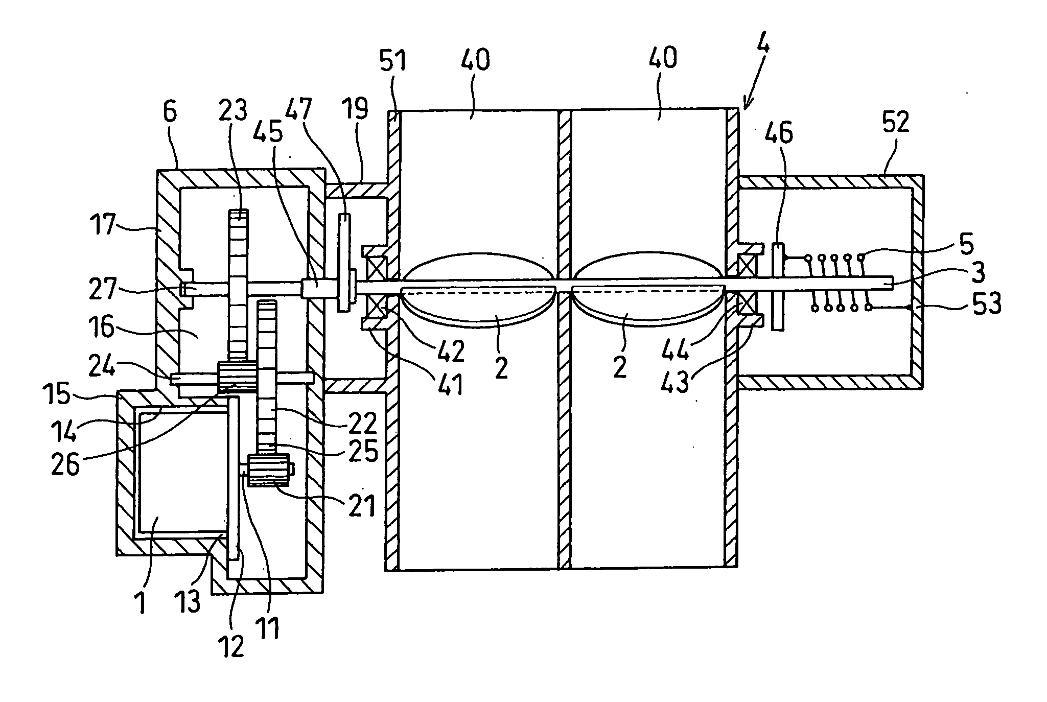
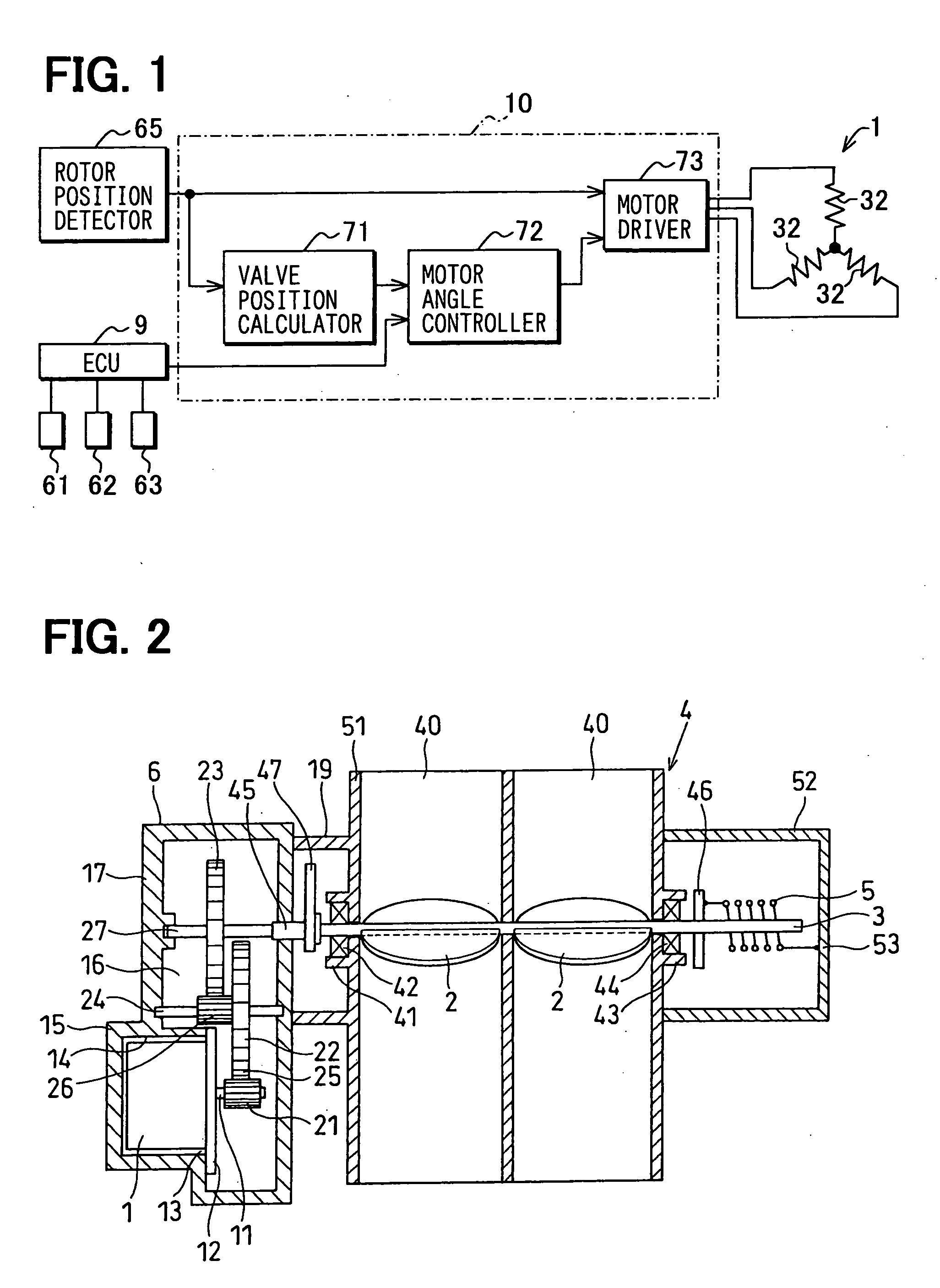
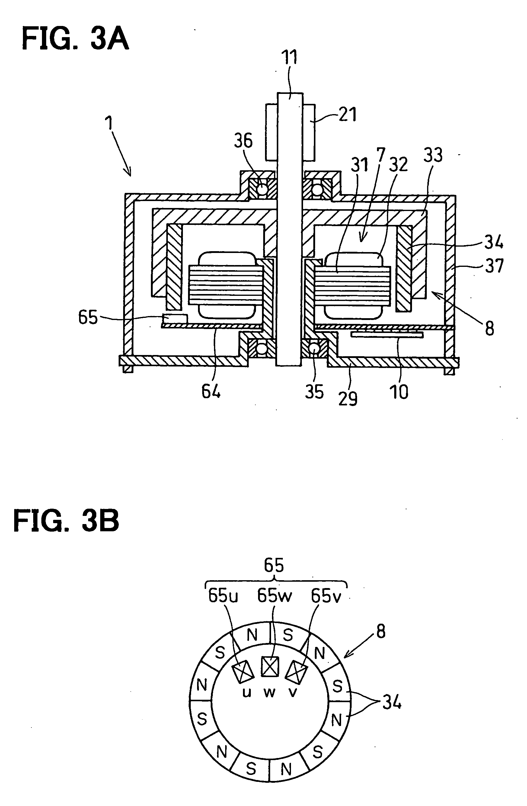
[0028] FIGS. 1 to 7 illustrate a first embodiment of the present invention, wherein FIG. 1 is a diagram illustrating a control logic of a motor current control circuit, FIG. 2 is a view schematically illustrating the constitution of a valve position controller for an internal combustion engine, and FIG. 3A is a view schematically illustrating the constitution of a brushless DC motor.

[0029] The valve position controller for an internal combustion engine according to this embodiment is a throttle position controller for the internal combustion engine, which is provided in the intake system of the internal combustion engine such as a multi-cylinder (four cylinder, in this embodiment) gasoline engine (hereinafter referred to as the engine) mounted on a vehicle such as an automobile, and works to vary the throttle position corresponding to the rotational angle of the throttle valve 2 by driving a brushless DC motor 1 in response to the amount that the accelerator pedal is depressed by a...

second embodiment

[0074]FIGS. 8A, 8B and 9 illustrate a second embodiment of the present invention, wherein FIG. 8A is a diagram illustrating the outputs of the Hall ICs under the normal condition, and FIG. 8B is a diagram illustrating the outputs of the Hall ICs under a temporarily malfunctioning condition due to noise.

[0075] Here, in the throttle position controller disclosed in JP-A-6-94151 and in Japanese Patent No. 3070292, in case the shift of the output condition of the rotor position detecting means 104 is skipped due to noise or the like, there may occur a large difference between the valve position that is recognized of the throttle valve and the real valve position of the throttle valve if there is provided no means for compensating the skipping and if the valve position of the throttle valve is calculated based on a signal output from the rotor position detection means 104. Depending upon the cases, further, the emission will be adversely affected.

[0076] Further, considered below is a c...

third embodiment

[0082]FIGS. 10 and 11 illustrate a third embodiment of the invention, wherein FIG. 10 is a diagram illustrating a control logic of a motor current control circuit having means for detecting the Hall IC that is malfunctioning, and FIG. 11 is a diagram illustrating the outputs of the normal Hall ICs.

[0083] In the valve position controller for the internal combustion engine of this embodiment, the three normal Hall ICs 65u, 65v and 65w can assume only six output conditions (six patterns) shown in FIG. 11, and the conditions {uvw}={000} and {uvw}={111} represent malfunctioning outputs or malfunctioning sensors. The motor current control circuit 10 of this embodiment has a malfunction detector 74 for detecting the malfunction (abnormal outputs or defective sensors) in the three Hall ICs 65u, 65v and 65w by detecting the signal conditions (ssta) output from the rotor position detector 65, i.e., by detecting malfunctioning conditions of the electric signals (sensor outputs) output from th...


PUM


Abstract

The throttle position corresponding to the rotational angle of the throttle valve is calculated based on electric signals output from a rotor position detector constituted by three Hall ICs that detect the rotational position of a magnet rotor of a brushless DC motor. A valve position control quantity of the throttle valve is so calculated as to eliminate the difference between the thus calculated valve position and a target valve position. The motor current control quantity of the brushless DC motor is so determined as to eliminate the difference between the calculated valve position and the target valve position. Though the throttle position sensor is omitted, the electric signals output from the rotor position detector are used for calculating both the valve position control quantity and the motor current control quantity.

Description

CROSS-REFERENCE TO RELATED APPLICATION [0001] This application is based on Japanese Patent Application No. 2004-212218 filed on Jul. 20, 2004, the disclosure of which is incorporated herein reference. FIELD OF THE INVENTION [0002] The present invention relates to a valve position controller for controlling the position of a valve based on a rotational position of a magnet rotor of a brushless motor. In particular, the invention relates to a valve position controller for controlling the position of a throttle that corresponds to the rotational angle of a throttle valve by driving the brushless motor in response to the amount that the accelerator is operated by a driver. BACKGROUND OF THE INVENTION [0003] There have heretofore been proposed electronically controlled throttle position controllers for electronically controlling the position of a throttle valve by driving a brushless DC motor depending upon the amount that the accelerator pedal is depressed (see, for example, JP-A-6-9415...

Claims


Application Information

Patent Timeline
Patent Type & Authority Applications(United States)
IPC IPC(8): F02D11/10
CPCF02D9/1095F02D2041/2058F02D41/20F02D11/106
Inventor UDA, TOSHIAKIKANDA, TSUYOSHIMURATA, TAISUKENAKAMURA, HIROSHI
Owner DENSO CORP
Why Eureka
Try Eureka