
Driver device for liquid crystal display, computer program and storage medium, and liquid crystal display

a technology of liquid crystal display and driver device, which is applied in the direction of static indicating device, non-linear optics, instruments, etc., can solve the problems of black mode motion blurriness and other display quality degradation, and achieve the effects of improving viewing angle characteristics and contrast ratio, image quality degradation, and maintaining contrast ratio

Active Publication Date: 2006-01-26
SHARP KK
View PDF14 Cites 37 Cited by
  • Summary
  • Abstract
  • Description
  • Claims
  • Application Information

AI Technical Summary

Benefits of technology

The present invention provides a driver device for liquid crystal displays that can improve image quality when displaying moving images while maintaining the contrast ratio achieved for still images. The device determines whether a pixel is in a moving image area and adjusts the grayscale level data accordingly to prevent insufficient response when displaying a moving image. This helps to avoid image quality degradation while maintaining the contrast ratio. The invention also includes a method for determining whether a pixel is in a moving image area based on the input video signal or information from a member processing the input video signal. The invention can be implemented in a computer program and associated liquid crystal display.

Problems solved by technology

However, liquid crystal displays which include as a display element a liquid crystal cell of vertically aligned mode and normally black mode can suffer motion blurriness and other display quality degradation when displaying moving images.

Method used


Image

  • Driver device for liquid crystal display, computer program and storage medium, and liquid crystal display
  • Driver device for liquid crystal display, computer program and storage medium, and liquid crystal display
  • Driver device for liquid crystal display, computer program and storage medium, and liquid crystal display

Examples


embodiment 1

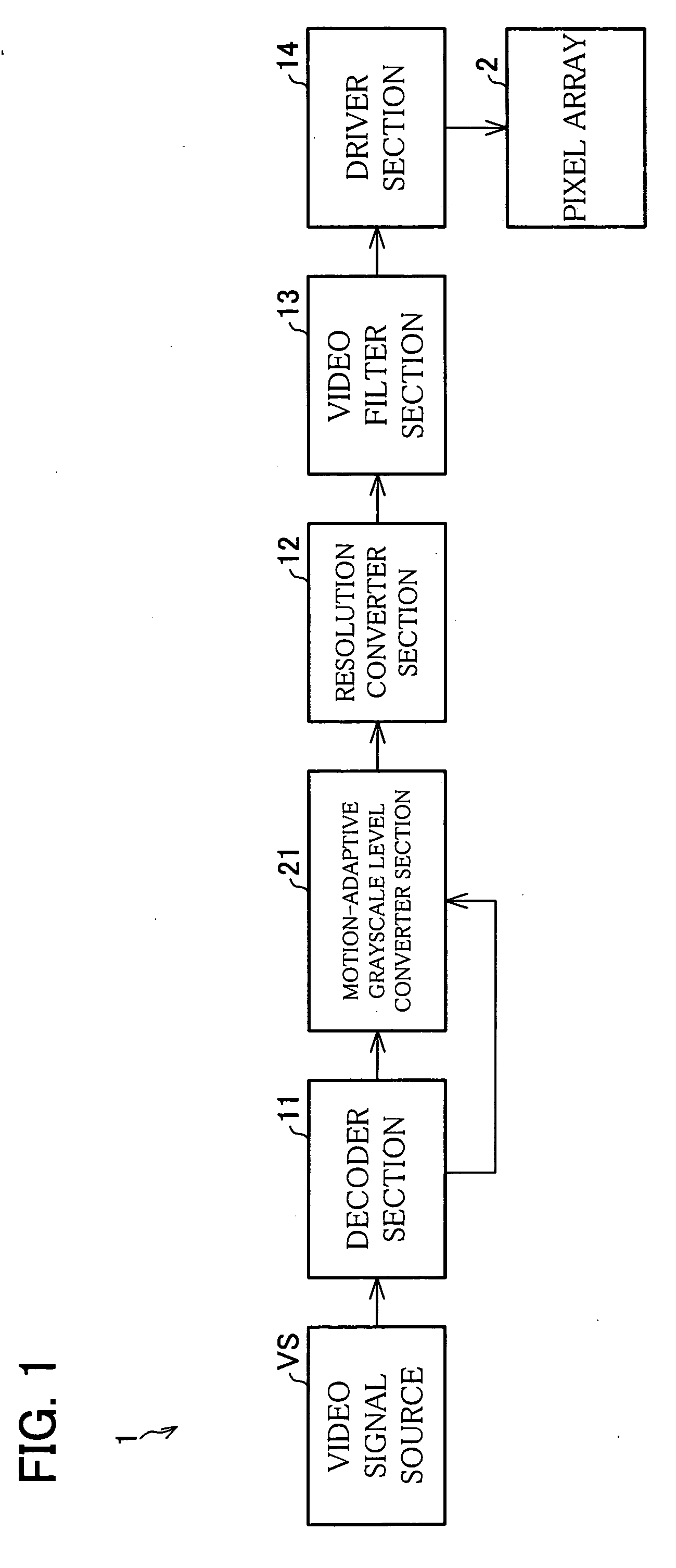
[0042] The following will describe an embodiment of the present invention in reference to FIG. 1 through FIG. 13. The image display in accordance with the present embodiment is built around a display element which is a liquid crystal cell of vertically aligned mode and normally black mode. The display is capable of preventing both motion blurriness and other display quality degradation of moving images and poor contrast ratio of still images. The display is suitable for use in television sets and computer monitors among other examples. The television set may receive broadcasts from terrestrial broadcasting, satellites, such as a digital BS (broadcast satellite) and a digital CS (communications satellite), and a cable, for example.

[0043] Referring to FIG. 1, an image display 1 in accordance with the present embodiment displays an image derived from a video signal representing a compressed image on a pixel array 2. The signal is fed from a video signal source VS. The display 1 contai...

embodiment 2

[0125] The first embodiment described a minimal movie region deciding process for decoding being used as a minimal movie region deciding process for grayscale level conversion. In contrast, the present embodiment will describe a minimal movie region deciding process for resolution conversion being used as a minimal movie region deciding process for grayscale level conversion. In the present embodiment, the decoder section 11 and the video filter section 13 may be omitted where they are not needed. The following description however assumes, as an example, that these members are included as in the first embodiment. The decoder section 11 is not needed when the input video signal DAT1 is uncompressed video signal (bitmap image video signal) for example, The video signal is fed to the resolution converter section 12.

[0126] An image display la in accordance with the present embodiment as shown in FIG. 14 has a substantially similar structure as in FIG. 1. The motion-adaptive grayscale l...

embodiment 3

[0133] The present embodiment will describe a minimal movie region deciding process for video filtering used as a minimal movie region deciding process for grayscale level conversion. In the present embodiment, the decoder section 11 and the resolution converter section 12 may be omitted where they are not needed. The following description however assumes, as an example, that these members are included as in the first embodiment.

[0134] An image display 1b in accordance with the present embodiment as shown in FIG. 15 has a substantially similar structure as in FIG. 1. The motion-adaptive grayscale level converter section 21 follows a video filter section 13b. The motion-adaptive grayscale level converter section 21 converts the grayscale levels given by the video signal DAT4 from the video filter section 13b based on information from the video filter section 13b. The video filter section 13b in the present embodiment is an equivalent to the video processing means in claims.

[0135] S...


PUM


Abstract

There is provided a motion-adaptive grayscale level converter section between a video signal source and a pixel array. The pixel array includes a liquid crystal cell of normally black and vertically aligned mode. The motion-adaptive grayscale level converter section determines based on information from a decoder section whether the pixels of an image represented by a video signal is in a moving image area. If a pixel is in a moving image area, the motion-adaptive grayscale level converter section changes the grayscale level data representing the grayscale level of the pixel so that there is no darker grayscale level than a predetermined first grayscale level. The resultant data is output as a video signal. Accordingly, we can provide a liquid crystal display capable of easing image quality degradation due to insufficient response when displaying a moving image while maintaining the contrast ratio achieved for a still image display.

Description

[0001] This Nonprovisional application claims priority under 35 U.S.C. § 119(a) on patent applications Ser. No. 2004-212186 filed in Japan on Jul. 20, 2004 and No. 2005-112891 filed in Japan on Apr. 8, 2005, the entire contents of which are hereby incorporated by reference.FIELD OF THE INVENTION [0002] The present invention relates to driver devices for liquid crystal displays which are capable of limiting image quality degradation due to insufficient response when displaying a moving image while maintaining a contrast ratio achieved for a still image display. The invention also relates to associated computer programs and storage media, as well as associated liquid crystal displays. BACKGROUND OF THE INVENTION [0003] Liquid crystal displays operating on relatively low electric power have found a wide range of applications as image displays for fixed types of devices, as well as for mobiles. Some of these liquid crystal displays include liquid crystal cells of vertically aligned mode...

Claims


Application Information

Patent Timeline
Patent Type & Authority Applications(United States)
IPC IPC(8): G09G3/36
CPCG09G3/3648G09G2320/0252G09G2340/0428G09G2340/0407G09G2320/10G02F1/133G09G3/36
Inventor SHIOMI, MAKOTO
Owner SHARP KK
Learn More