General line of sight stabilization system

a stabilization system and general line of sight technology, applied in the field of optical systems, can solve problems such as the limitation of mechanized motor control, and achieve the effect of minimizing the weight of the entire system and minimizing the cos

Inactive Publication Date: 2006-01-26
OPTO KNOWLEDGE SYST
View PDF14 Cites 40 Cited by
  • Summary
  • Abstract
  • Description
  • Claims
  • Application Information

AI Technical Summary

Benefits of technology

[0018] By deflecting only the photons of the scene (passive imaging) or source (active imaging), the inventive system avoids the need to stabilize the entire imaging sensor and optics system. The only mass to move is that of the two imaging system mirrors. This approach requires small motors with low torque, providing a less expensive, lightweight, and small image orientation and stabilization system.
[0021] The invention additionally encompasses calculation instructions and optionally calculation hardware for determining the coupled movement of the two mirror system, making possible the object of using a compact, independent image orientation and stabilization system capable of working with a wide variety of imaging systems and carriers (helicopters, airplanes, satellites, and others). The invention also makes possible the object of upgrading and retrofitting existing image acquisition systems at minimal cost.
[0023] Additionally, an object of the invention is to provide a orientation and stabilization method for ultraspectral imaging, using the inventive mirror control method to provide forward motion compensation, allowing the imaging system to receive a stable, continuous, non-moving image for a sufficient time to acquire data for a relatively long exposure time as required for subsequent Fourier transformation.

Problems solved by technology

The inventive system limits mechanized motor control to the moving of two pivoted, and relatively small, mirrors.

Method used


Image

  • General line of sight stabilization system
  • General line of sight stabilization system
  • General line of sight stabilization system

Examples


Embodiment Construction

[0029] The following detailed description illustrates the invention by way of example, not by way of limitation of the principles of the invention. This description will clearly enable one skilled in the art to make and use the invention, and describes several embodiments, adaptations, variations, alternatives, and uses of the invention, including what are presently believed to be the best modes of carrying out the invention.

[0030] In this regard, the invention is illustrated in the several figures and is of sufficient complexity that the many parts, interrelationships, process steps, and sub-combinations thereof simply cannot be fully illustrated in a single patent-type drawing or table. For clarity and conciseness, several of the drawings show particular elements in schematic and omit other parts or steps that are not essential in that drawing to a description of a particular feature, aspect, or principle of the invention being disclosed.

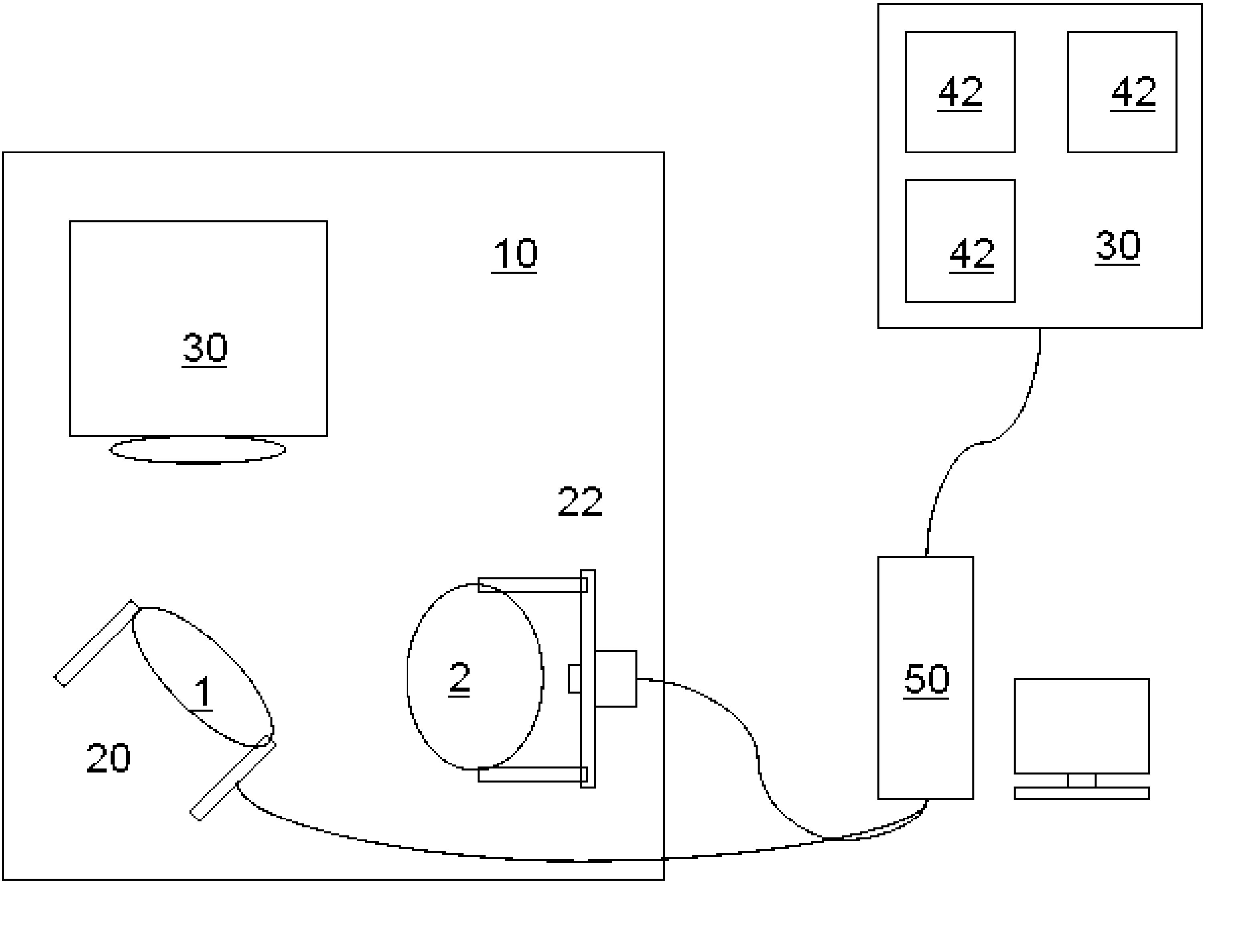
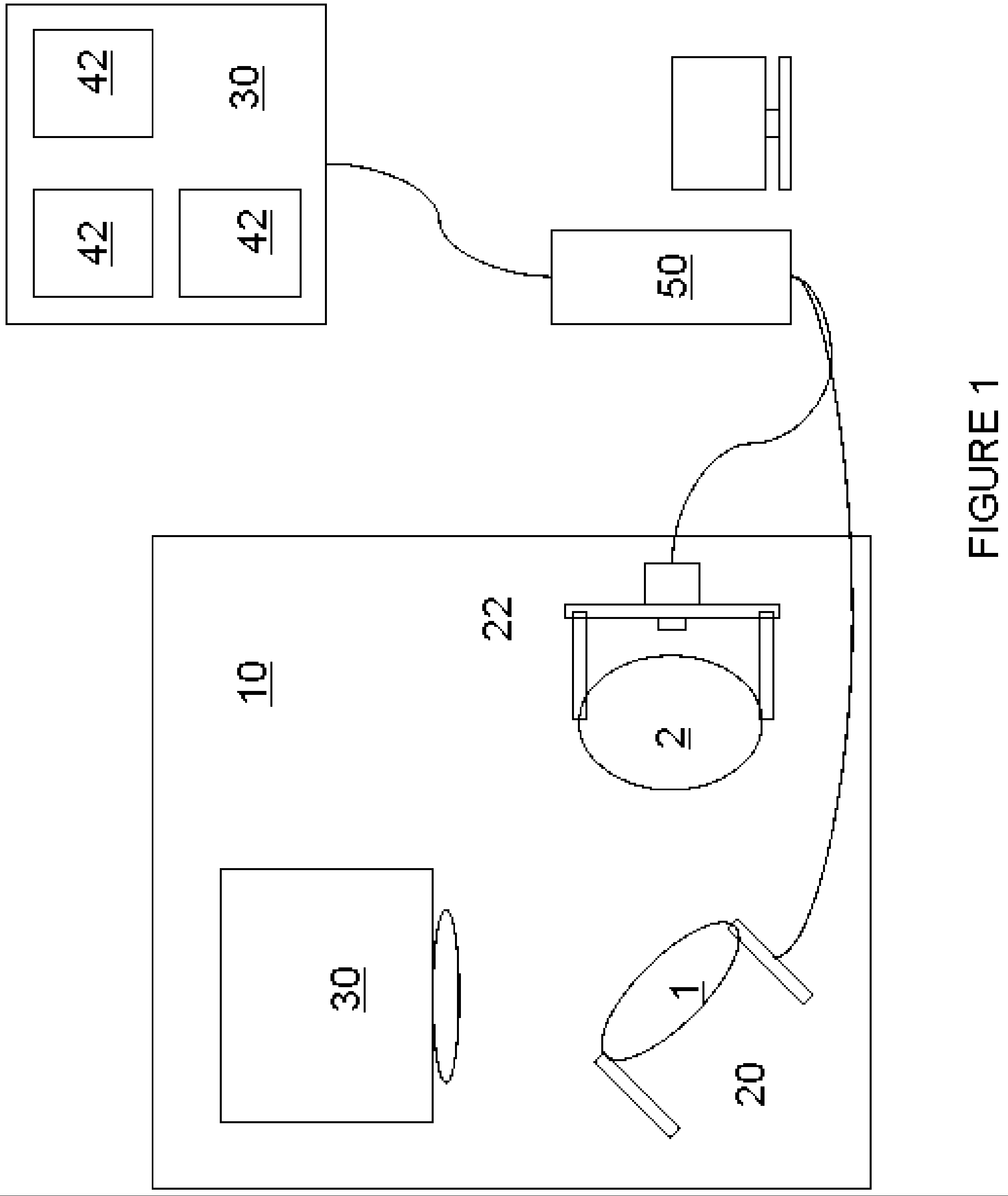
[0031] The inventive GLOSS system is gene...


PUM


Abstract

A line of sight stabilization system using two mirrors pivotally mounted to a fixed platform that can be used with existing imaging systems to provide pitch, roll, and yaw compensation while maintaining image orientation. By deflecting only the photons, the inventive system avoids the need to stabilize the entire imaging sensor and optics system. The only mass to move is that of the two imaging system mirrors. By monitoring attitude changes via an inertial measurement system, proceeding platform positions can be estimated for subsequent image acquisitions, and efficient mirror positioning can provide optimal image orientation and stabilization. This approach requires small motors with low torque, providing a less expensive, lightweight, and small image orientation and stabilization system.

Description

FEDERAL RESEARCH STATEMENT [0001] This invention was made with U.S. Government support under NASA NAS 13-03014. The U.S. Government has a royalty-free right to the use of this invention.BACKGROUND OF INVENTION [0002] 1. Field of the Invention [0003] The invention relates to optical systems and their elements, and to image orientation and stabilization. More particularly, the invention is directed to line of sight image stabilization by way of movable reflective structures such as mirrors. In particular, the invention concerns hyperspectral and other optical passive and active imaging systems that can benefit from three axes image stabilization as well as orientation, such as airborne and spaceborne (off-nadir viewing) imaging systems. The apparatus of the invention shows particular utility for use with airborne and spaceborne pushbroom hyperspectral and, with forward motion compensation, ultraspectral imaging systems, agricultural and military applications, or in any other applicati...

Claims


Application Information

Patent Timeline
IPC IPC(8): H04N5/228
CPCG01S7/4811H04N5/232G02B27/644H04N23/60
Inventor GAT, NAHUM
Owner OPTO KNOWLEDGE SYST
Why Eureka
Try Eureka