Optical measuring device

a measuring device and optical technology, applied in the field of optical measuring devices, can solve the problems of increased measurement errors, easy contamination of projectors and photoreceptors, and increased measurement errors, so as to improve the accuracy of abnormality detection

Inactive Publication Date: 2006-01-26
MITUTOYO CORP
View PDF10 Cites 38 Cited by
  • Summary
  • Abstract
  • Description
  • Claims
  • Application Information

AI Technical Summary

Benefits of technology

[0013] In the present invention, when an abnormality arises on the optical path of the beam, the abnormality is detected based on the fact that a difference

Problems solved by technology

The projector and the photoreceptor contain expensive optical components (such as a semiconductor laser, photodiodes, lenses and mirrors).
The protective glass is exposed to the externa

Method used


Image

  • Optical measuring device
  • Optical measuring device
  • Optical measuring device

Examples


Embodiment Construction

[0019] An embodiment of the present invention will now be described in detail below with reference to the drawings.

[Configuration of Optical Measuring Device]

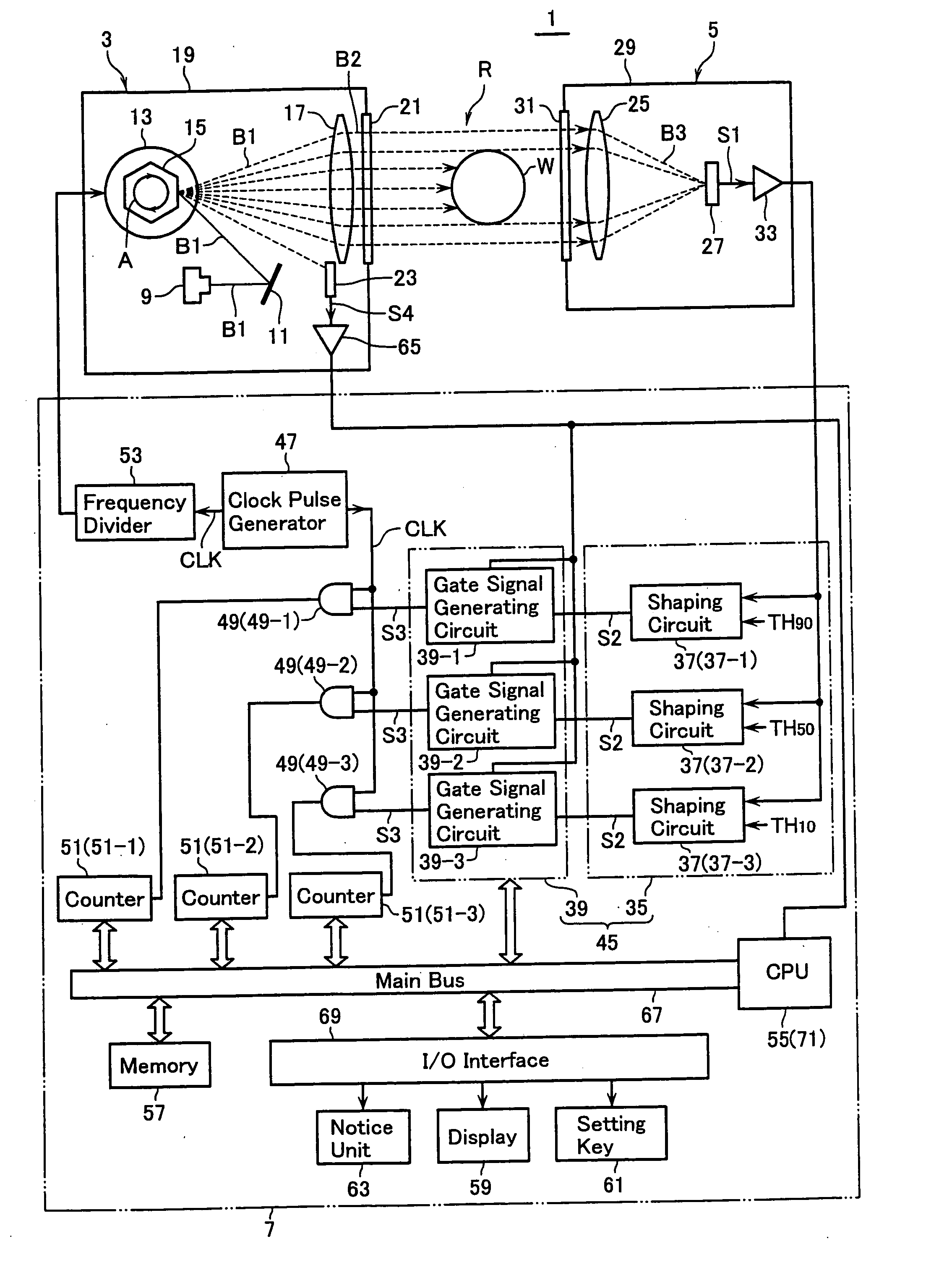
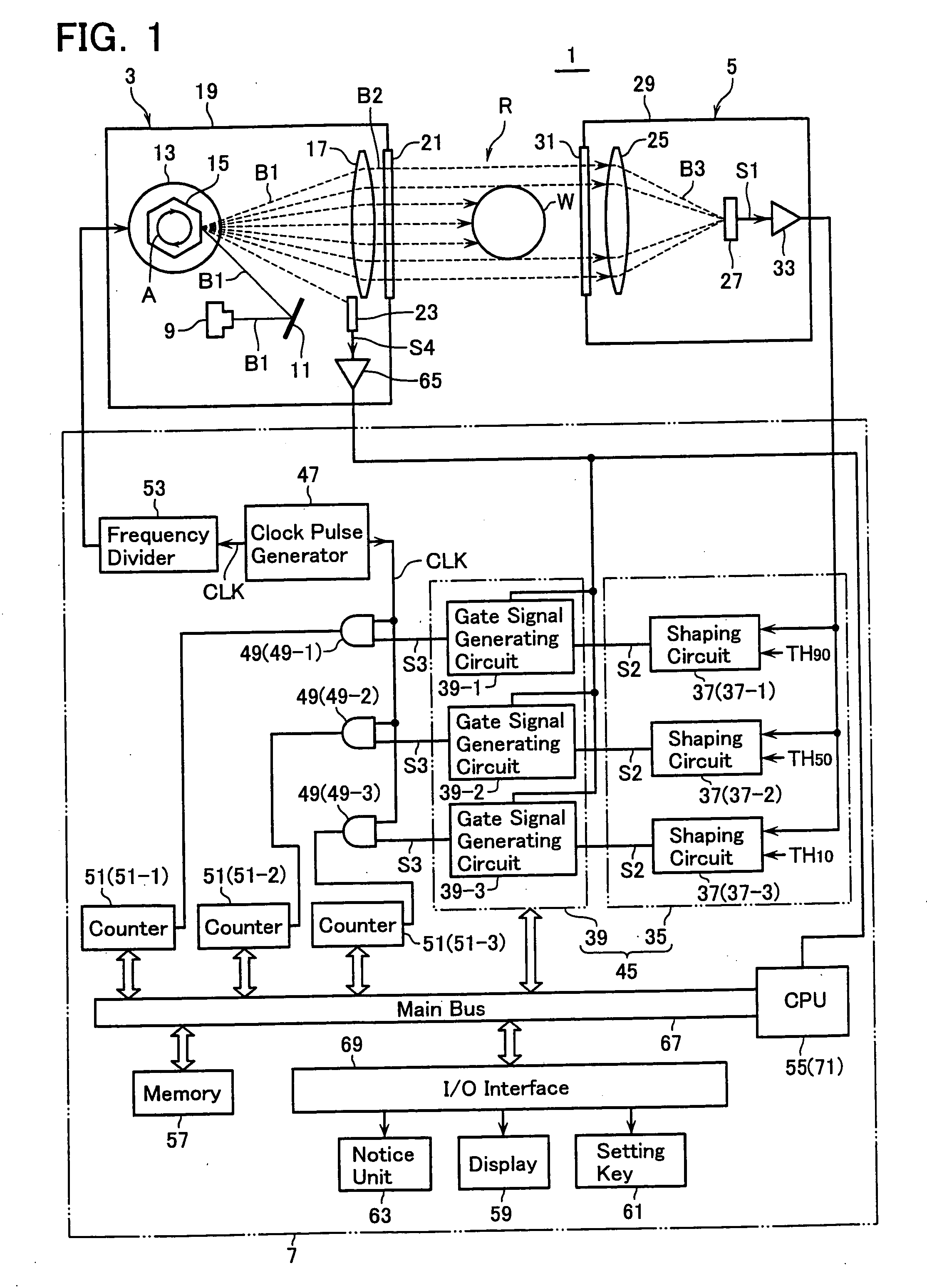
[0020]FIG. 1 is a block diagram illustrative of an optical measuring device 1 according to the embodiment. The device 1 comprises a projector 3, a photoreceptor 5 and a controller 7. The projector 3 opposes to the photoreceptor 5 with a scan region R sandwiched therebetween. The scan region R is a region located in an external ambient, which is employed to locate a work W to be measured. The controller 7 is connected to the projector 3 and the photoreceptor 5 through cables (not shown) to execute various controls required for measurements.

[0021] The projector 3 includes a light-emitting element 9 such as a semiconductor laser, and a mirror 11 operative to reflect a beam B1 emitted from the element 9. It also includes a polygon mirror 15 operative to receive the beam B1 reflected from the mirror 11 while it is rotated at a hi...


PUM


Abstract

An optical measuring device capable of improving the precision of detection of contamination on a protective glass is disclosed. With threshold values as large as 90%, 50%, 10% of a peak value of a scan signal, measured values Q90, Q50, Q10 of a dimension of a work to be measured are derived, respectively. It is determined whether a difference between the measured value Q90 and the measured value Q50 (or a variation of the measured value) is equal to or larger than a predetermined reference value. (B)-(D) show the presence of contamination on the protective glass, equal to or larger than the reference value. (A) shows the absence of contamination, lower than the reference value. It is then determined whether a difference between the measured value Q50 and the measured value Q10 is equal to or larger than a predetermined reference value. (D) shows the presence of thick contamination on the protective glass, equal to or larger than this reference value. Accordingly, a buzzer is driven and a red lamp is turned on to give the alarm to the operator to remove the contamination immediately.

Description

CROSS-REFERENCE TO RELATED APPLICATION [0001] This application is based upon and claims the benefit of priority from the prior Japanese Patent Application No. 2004-214624, filed on Jul. 22, 2004, the entire contents of which are incorporated herein by reference. BACKGROUND OF THE INVENTION [0002] 1. Field of the Invention [0003] The present invention relates to an optical measuring device of a scanning type that uses a collimated beam. [0004] 2. Description of the Related Art [0005] An optical measuring device comprises a projector and a photoreceptor located separately by a scan region in which a work to be measured locates. A collimated beam from the projector is employed to repeatedly scan the scan region and the photoreceptor receives the beam transmitted through the scan region to generate scanned signals. The scanned signals are specifically processed to indicate a measured value (such as a dimension and roundness of the work to be measured). [0006] The projector and the photo...

Claims


Application Information

Patent Timeline
IPC IPC(8): G01B11/02G01B11/08G01B11/24G01N21/88
CPCG01B11/2433G01B11/08
Inventor TAKAYAMA, YASUHARUI
Owner MITUTOYO CORP
Why Eureka
Try Eureka