Laser module with sealed package containing limited optical components

Inactive Publication Date: 2006-01-26
ADTEC ENG +1
View PDF18 Cites 54 Cited by
  • Summary
  • Abstract
  • Description
  • Claims
  • Application Information

AI Technical Summary

Benefits of technology

[0046] (6) In the case where the first package is hermetically sealed by one of fusion, welding, soldering using a flux-free solder, and adhesion using an adhesive which does not contain a silicon-based organic material, it is possible to suppress emanation of volatile components which causes contamination, and prevent contamination of the semiconductor laser elements and the like.
[0047] (7) In the case where the first package is filled with inert gas, it is possible to prevent entry of contaminated gas into the first package. Further, in the case where the inert gas contains one or a mixture of oxygen gas, halogen gas, and halide gas at a concentration of 1 ppm or higher, the effect of preventing contamination is enhanced since oxygen gas, halogen gas, and halide gas cause decomposition of hydrocarbon components and the like.
[0048] (8) In the case where the light-entrance end face of the optical fiber is contained in another package (the third package) which is hermetically sealed, it is possible to prevent dust collection at the light-entrance end face although the optical density is likely to become high. In this case, it is possible to arrange the first package and the third package in such a manner that the total volume of the first and third packages is smaller than the volume of a large, hermetically sealed package which contains all the constituents of the laser module. Therefore, the cost can be reduced by

Problems solved by technology

In the laser modules as mentioned above, contaminants remaining in the hermetically sealed package are likely to be deposited on the light-emission end face of the semiconductor laser element and other optical components such as the optical condensing system and the optical fiber, so that the laser characteristics deteriorate.
The laser light polymerizes or decomposes such hydrocarbon compounds, and the materials produced by the polymerization or decomposition are deposited and impede increase in the optical output power.
Therefore, chemical components are outgassed during the degassing operation, and thus the inside of the laser module is contaminated with the outga

Method used


Image

  • Laser module with sealed package containing limited optical components
  • Laser module with sealed package containing limited optical components
  • Laser module with sealed package containing limited optical components

Examples


Example

First Embodiment

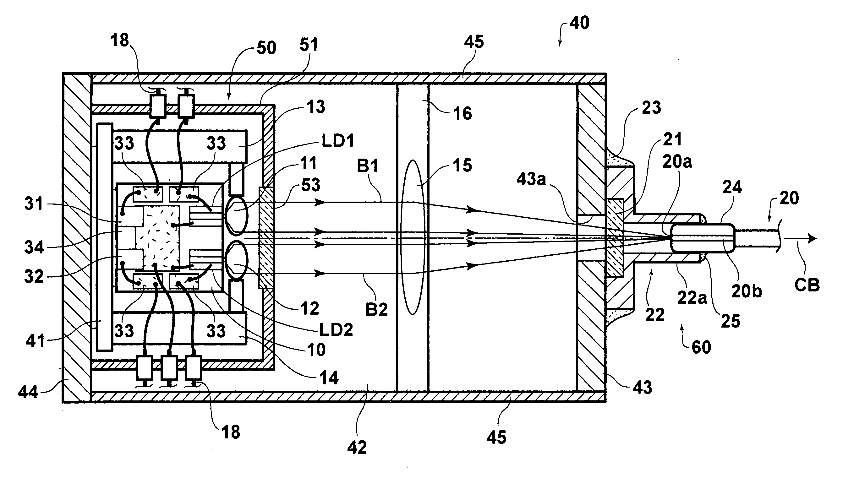
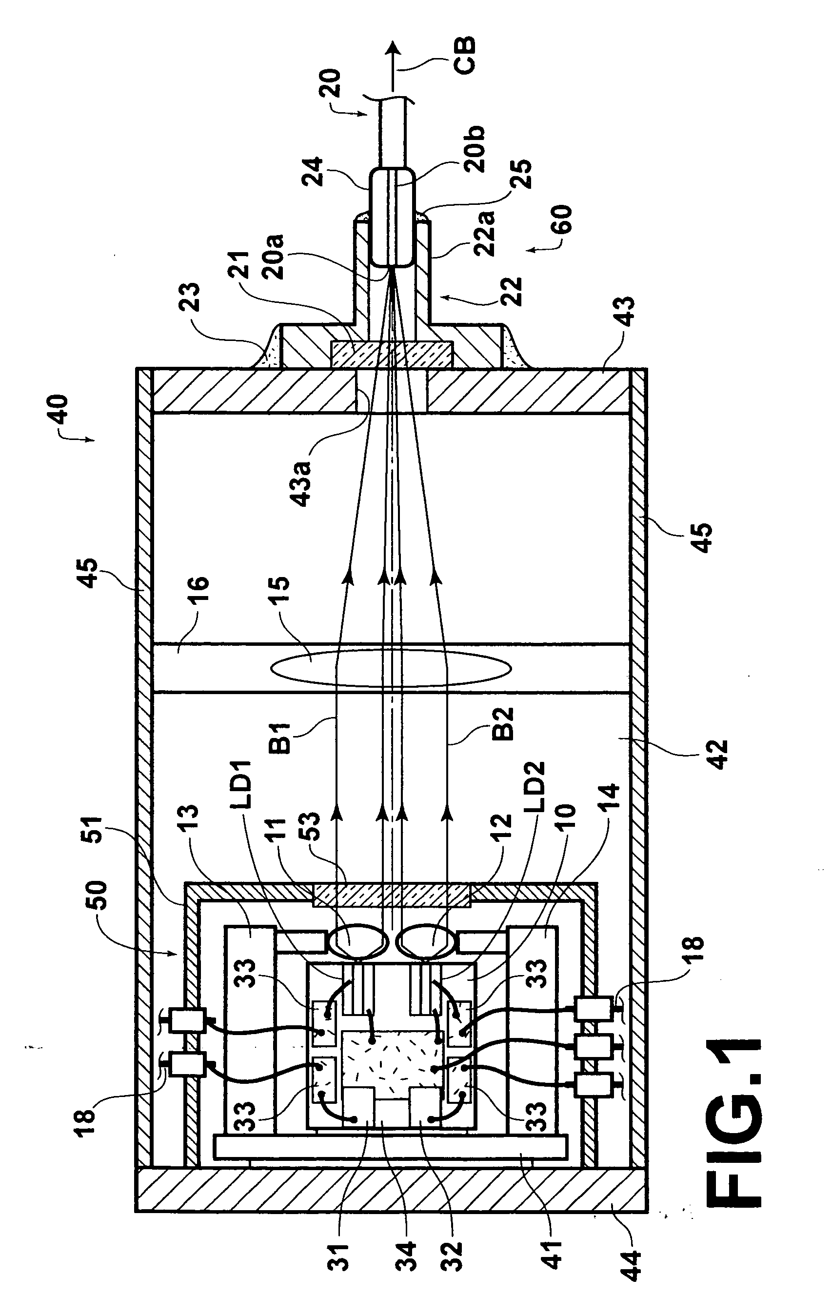
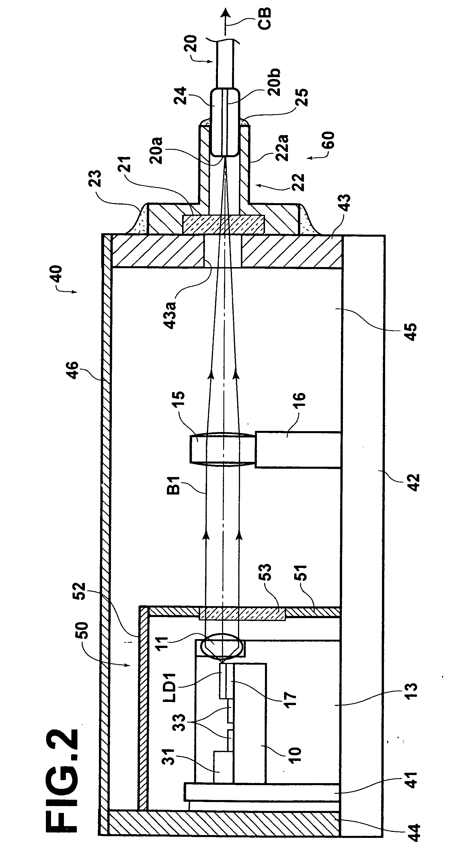
[0070]FIGS. 1 and 2 are respectively plan and side views, partly in cross section, of a laser module according to the first embodiment of the present invention.

[0071] As illustrated in FIGS. 1 and 2, the laser module according to the first embodiment comprises a plurality (e.g., two) of semiconductor lasers LD1 and LD2, a heat block (heat-dissipation block) 10, a plurality (e.g., two) of collimator lenses 11 and 12, a plurality (e.g., two) of collimator-lens holders 13, and 14, a condensing lens 15, a condensing-lens holder 16, and an optical fiber 20. The semiconductor lasers LD1 and LD2 are fixed on the upper surface of the heat block 10. The collimator lenses 11 and 12 collimate divergent laser beams B1 and B2 emitted from the semiconductor lasers LD1 and LD2. The collimator-lens holders 13 and 14 respectively hold the collimator lenses 11 and 12. The condensing lens 15 condenses the collimated laser beams B1 and B2 so that the laser beams B1 and B2 converge at ...

Example

Second Embodiment

[0113] Hereinbelow, the second embodiment of the present invention is explained with reference to FIG. 3, which is a plan view, partly in cross section, of a laser module according to the second embodiment of the present invention.

[0114] The laser module according to the second embodiment is basically different from the first embodiment in that magnifying condenser lenses 61 and 62 are used instead of the collimator lenses 11 and 12 and the condensing lens 15, and the light-source package 50 contains the semiconductor lasers LD1 and LD2 and the magnifying condenser lenses 61 and 62. In addition, in the second embodiment, the photodiodes 31 and 32, which are arranged in the first embodiment for monitoring the backward emission light, are not used.

[0115] As illustrated in FIG. 3, in the laser module according to the second embodiment, the laser beams B1 and B2 emitted from the semiconductor lasers LD1 and LD2 are respectively collimated by the magnifying condenser ...

Example

[0177]FIG. 9 is a plan view of a portion of a laser module according to the third embodiment of the present invention. In the laser module according to the third embodiment, as illustrated in FIG. 9, eight semiconductor laser elements are stacked in upper and lower layers. Specifically, four semiconductor laser elements LD11, LD12, LD13, and LD14 are arranged along the horizontal direction in the upper layer, and four semiconductor laser elements LD21, LD22, LD23, and LD24 are arranged along the horizontal direction in the lower layer.

[0178] Divergent laser beams B11, B12, B13, B14, B21, B22, B23, and B24 emitted from the semiconductor laser elements LD11, LD12, LD13, LD14, LD21, LD22, LD23, and LD24 are respectively collimated by collimator lenses C11, C12, C13, C14, C21, C22, C23, and C24, and condensed by first and second cylindrical lenses 80 and 81 so as to converge on the light-entrance end face 20a of the optical fiber 20. Therefore, the laser beams B1, B12, B13, B14, B21, B...


PUM


Abstract

A laser module includes: one or more semiconductor laser elements which emit one or more divergent laser beams; one or more collimator lenses which collimate the one or more divergent laser beams; a condensing lens which condenses the one or more collimated laser beams, and make the one or more collimated laser beams converge at a convergence position; an optical fiber which is arranged in such a manner that the convergence position is located on the light-entrance end face; and a package which contains the one or more semiconductor laser elements and the one or more collimator lenses, does not contain the condensing lens and the light-entrance end face, and is hermetically sealed.

Description

BACKGROUND OF THE INVENTION [0001] 1. Field of the Invention [0002] The present invention relates to a laser module in which a laser beam emitted from a semiconductor laser element is coupled to an optical fiber. [0003] 2. Description of the Related Art [0004] Conventionally, the laser modules having the following construction are known as the pigtail-type laser modules, and widely used in the field of optical communications. The pigtail-type laser modules are constituted by a semiconductor laser element contained in a package, an optical fiber being fixed to the package and having an end which appears inside the package, and an optical condensing system which couples a laser beam emitted from the semiconductor laser element with a light-entrance end face. [0005] As a variation of the above pigtail-type laser modules, the combined-laser modules are also known, for example, as indicated in Japanese Unexamined Patent Publication No. 2003-298170. In the combined-laser modules, a plural...

Claims


Application Information

Patent Timeline
IPC IPC(8): G02B6/36
CPCG02B6/4248G02B6/4204
Inventor SONODA, SHINICHIRONAGANO, KAZUHIKOMIURA, HIDEO
Owner ADTEC ENG
Why Eureka
Try Eureka