
Manufacture of papermachine fabrics

Inactive Publication Date: 2006-01-26
VOTH FABRICS PATENT GMBH
View PDF4 Cites 99 Cited by
  • Summary
  • Abstract
  • Description
  • Claims
  • Application Information

AI Technical Summary

Benefits of technology

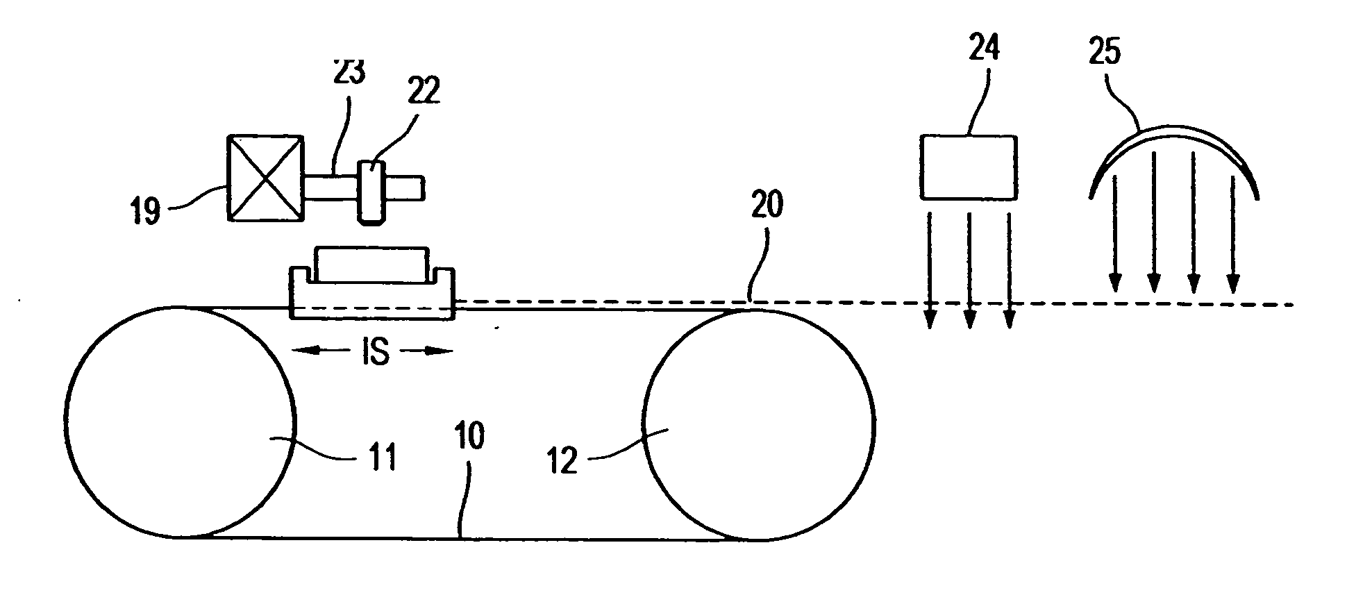
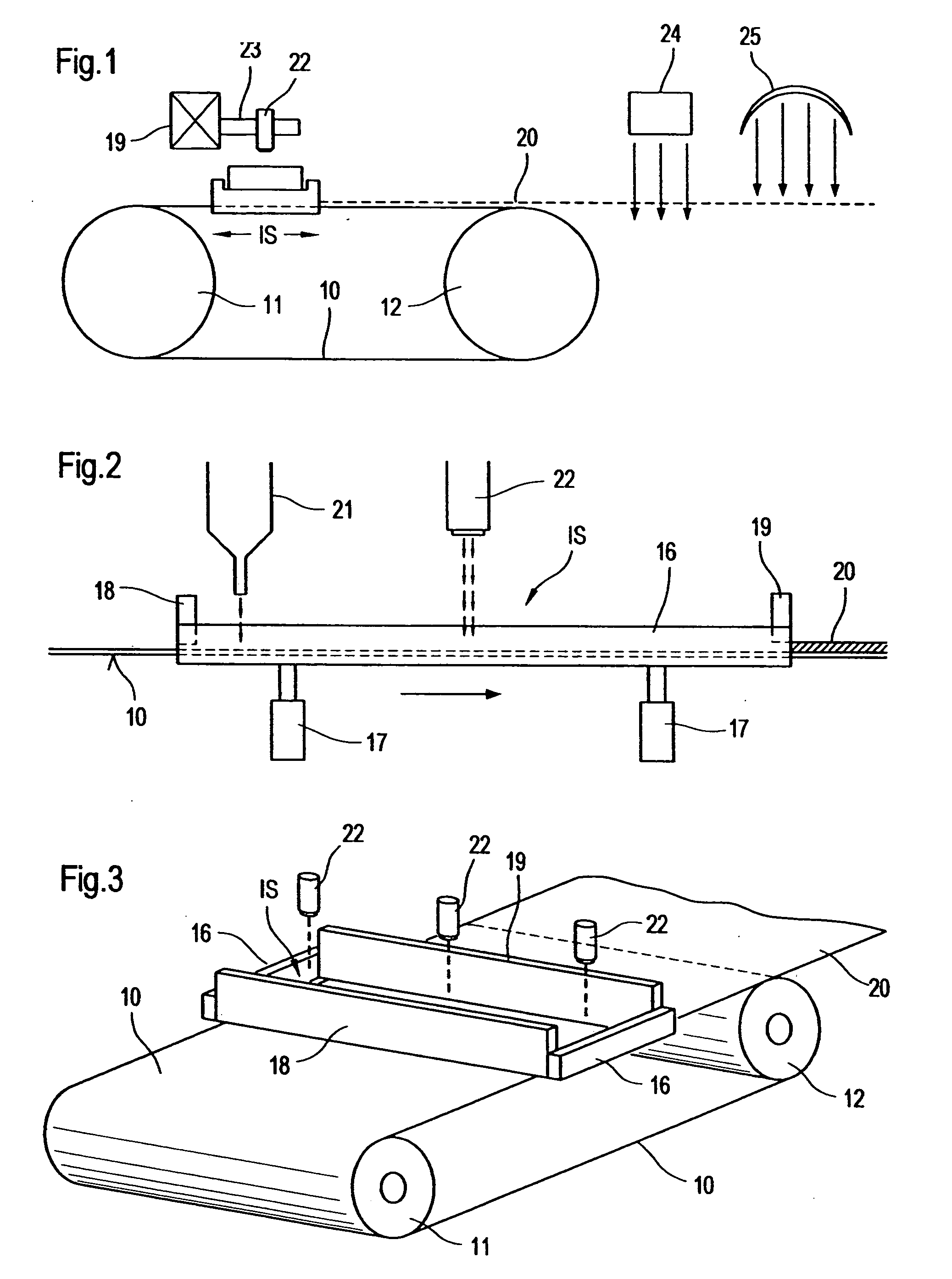
[0027] The extended working surface is required to be large enough to allow formation of full size paper machine fabrics, which can measure up to 11 m by 30 m. The work surface may comprise an endless belt, preferably coated with a non-stick PTFE coating and having a width equal to or somewhat greater than the papermachine fabric to be fabricated. The fabric may be built up in zones extending across the width of the belt, with each zone being integrated by the deposition and treatment process with the previous zone, repeating the layer by layer building up in each zone in turn to form a fabric of any desired length. The fabric may be peeled off from the endless belt and taken up for later seaming, or the seaming problem avoided by forming the fabric as an endless belt of similar dimensions to the working surface belt, and removing it from the working surface belt.
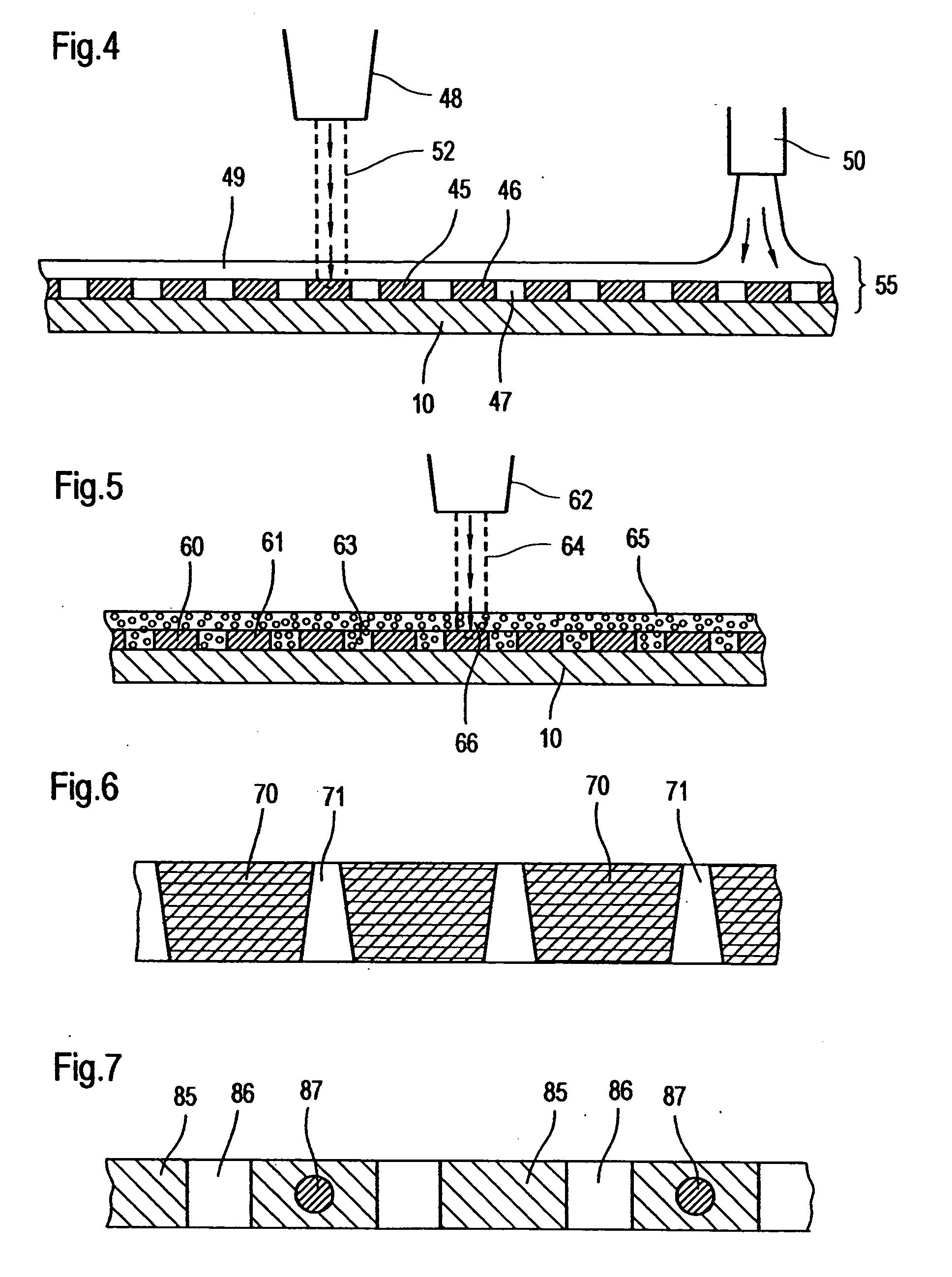
[0031] The method of manufacture according to the invention, provides the possibility to produce non-woven papermachine fabrics according to almost any traditional or innovative design, or to produce non-woven webs for use as components in composite fabrics, for example as base layers in press felts.

Problems solved by technology

This problem is particularly apparent at the wet end of the papermachine where the sheet is still highly plastic.
Many of these have been impractical to manufacture commercially.
Such an arrangement is not durable and consequently this fabric is not commercially viable.
Such an arrangement, if ever commercialized, would exhibit poor wear resistance.
Link belts are only suitable for certain applications, due to calliper and material restrictions.
Such sheets are composed of unoriented polymer material, and if produced in the fineness needed for papermaking applications, would lack sufficient dimensional stability to operate as endless belts on papermachines.
This is undesirable for adaptation to paper sheet formation, where controlled dewatering is required, especially during the delicate sheet forming phase.
This is undesirable for paper sheet formation and additionally permits the occurrence of harmful “backwash” which comes from hydraulic pulses passing through the fabric from the machine side.
The direct passage of these pulses disturbs the fragile cellulosic fibrous network.

Method used


Image

  • Manufacture of papermachine fabrics
  • Manufacture of papermachine fabrics
  • Manufacture of papermachine fabrics

Examples


Embodiment Construction

[0056] The particulars shown herein are by way of example and for purposes of illustrative discussion of the embodiments of the present invention only and are presented in the cause of providing what is believed to be the most useful and readily understood description of the principles and conceptual aspects of the present invention. In this regard, no attempt is made to show structural details of the present invention in more detail than is necessary for the fundamental understanding of the present invention, the description taken with the drawings making apparent to those skilled in the art how the several forms of the present invention may be embodied in practice.

[0057]FIGS. 1, 2 and 3 illustrate an embodiment of apparatus which may be used in a method according to the invention for the manufacture of papermachine fabrics, either by use of a UV-curable resin, or by sintering of a particulate thermoplastic material.

[0058] The apparatus comprises an endless belt 10 provided on te...


PUM

PropertyMeasurementUnit
Thicknessaaaaaaaaaa
Widthaaaaaaaaaa
Heightaaaaaaaaaa

Abstract

Paper machine clothing method including covering an extended working surface with successive layers of a resultant material. Treating each successive layer with an energy source in accordance with predetermined instructions before adding a next successive layer to build up a three-dimensional fabric structure. The instant abstract is neither intended to define the invention disclosed in this specification nor intended to limit the scope of the invention in any way.

Description

CROSS-REFERENCE TO RELATED APPLICATIONS [0001] The present application claims priority under 35 U.S.C. §119 of German Patent Application No. 10 2004 035 369.7, filed on Jul. 21, 2004, the disclosure of which is expressly incorporated by reference herein in its entirety. BACKGROUND OF THE INVENTION [0002] 1. Field of the Invention [0003] The invention relates to the manufacture of papermachine fabrics such as forming fabrics, press felts, dryer fabrics, through-air dryer (TAD) fabrics and other industrial fabrics, such as hydroentanglement screens and transfer fabrics for use in a papermachine. [0004] 2. Discussion of Background Information [0005] Paper is conventionally manufactured by conveying a paper furnish, usually composed of an initial slurry of cellulosic fibers, on a forming fabric or between two forming fabrics in a forming section, the nascent sheet then being passed through a pressing section and ultimately through a drying section of a papermaking machine. In the case o...

Claims


Application Information

Patent Timeline
IPC IPC(8): B32B5/08D21F1/00D21F7/08
CPCD21F7/083D21F1/0063Y10T442/3301
Inventor SAYERS, IAN
Owner VOTH FABRICS PATENT GMBH
Learn More