Pest control method and apparatus therefor

a technology for pests and apparatus, applied in the field of pest control, can solve the problems of contaminating the environment and consequentially affecting human and animal health, and achieve the effect of reducing the number of pests

Inactive Publication Date: 2006-02-02
EXOSECT
View PDF25 Cites 26 Cited by
  • Summary
  • Abstract
  • Description
  • Claims
  • Application Information

AI Technical Summary

Benefits of technology

[0006] Accordingly, it is an object of the present invention to provide various methods of and means for controlling pests, such as flying or crawling insect pests, which overcome, or at least substantially reduce, the disadvantages associated with the known pest control methods discussed above.

Problems solved by technology

The constant pressure of pesticide use in agriculture can lead to the development of pesticide-resistance amongst insect pest species, resulting in the killing of non-target animals including beneficial predators and parasites which tend to maintain a natural balance of the pest species.
Also, it leads to the contamination of the environment with consequential harmful effects on human and animal health, resulting from exposure to pesticide residues in water and comestible products.

Method used


Image

  • Pest control method and apparatus therefor
  • Pest control method and apparatus therefor
  • Pest control method and apparatus therefor

Examples


second embodiment

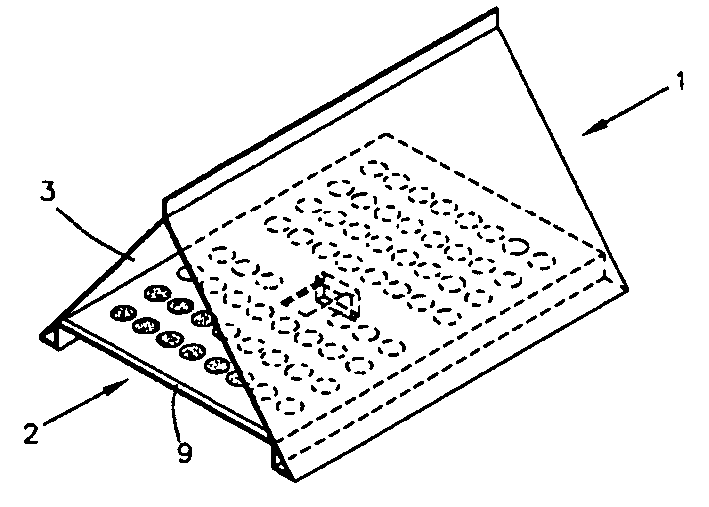
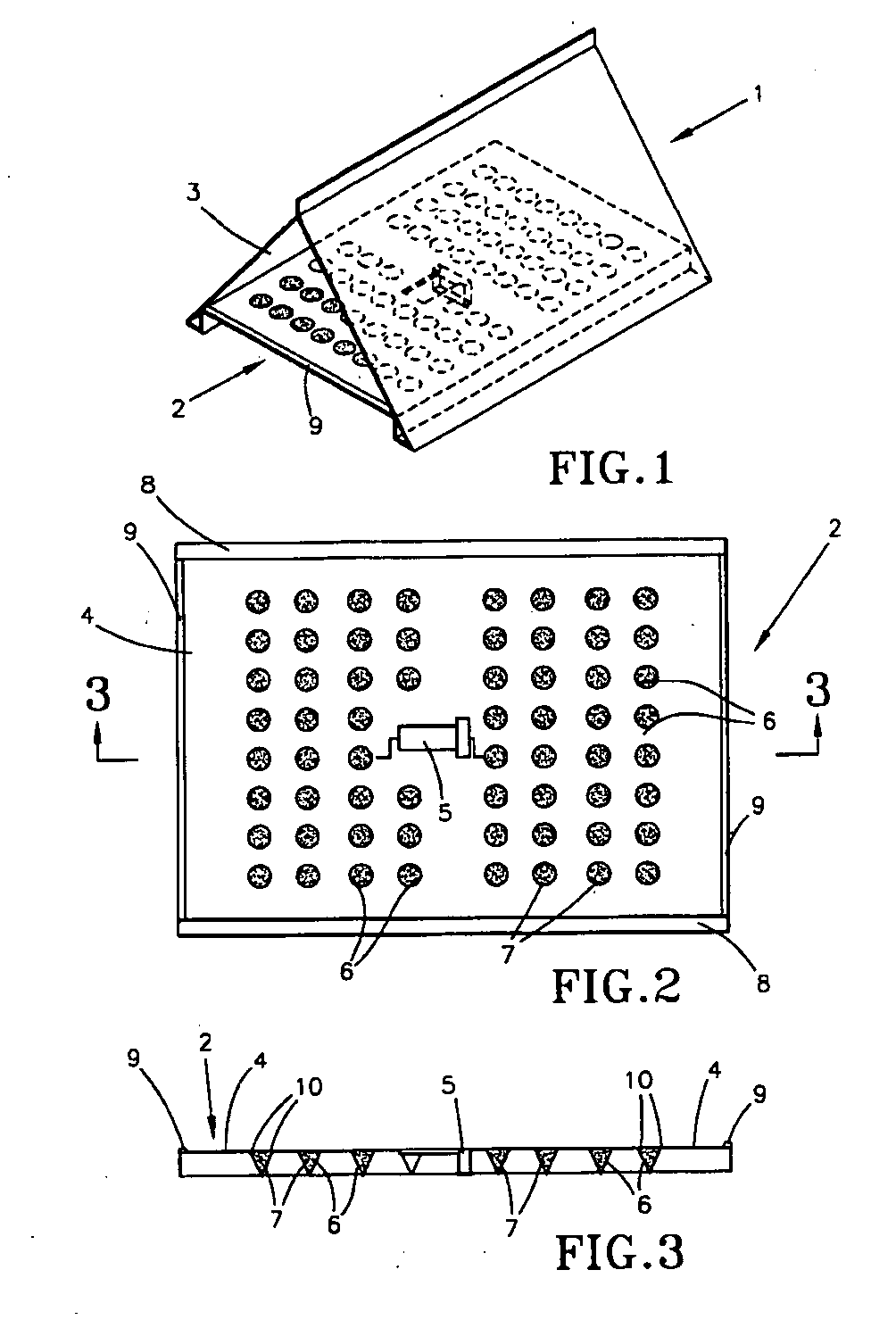
[0056] Such a vertical orientation of the plate and associated powder-bearing surface is shown in a flying insect pest monitoring trap 21 in FIGS. 4 and 5. This vertical orientation of powder-bearing surfaces 24 of a base plate 22 is, in certain circumstances, desirable because some species of flying insect pest, for example, the olive fruit fly, land preferentially on vertical surfaces.

[0057] In the second embodiment of the flying insect pest monitoring trap 21 shown in FIGS. 4 and 5, the opposed vertical surfaces 24 of the plate 22 are again provided with recesses, this time in the form of troughs 26, in which is accommodated, once again, a pest-killing or behavior-modifying powder 27 which, as described in reference to the first embodiment, is capable of being rendered airborne and electrostatically charged as a result of the wing beats or other movements of flying insect pests in the region thereof.

first embodiment

[0058] The trap 21 is provided with a roof 23 for preventing rainwater from accumulating in the troughs 26, while a source 25 of odor attractant, such as that discussed above in relation to FIGS. 1 to 3, is provided at the upper region of the plate 22.

[0059] Thus, flying insect pests are attracted to the trap 21 by a combination of visual features, including color, and the odor attractant 25, again as in the case of the first embodiment.

[0060] The troughs 26 in which the powder 27 is accommodated, may be placed at an angle to their respective surfaces 24, or, as shown in FIGS. 4 and 5, may be in the form of cup or trough-shaped projections, namely, the troughs 26.

[0061] The shape of the powder-accommodating recesses 6 of the first embodiment of the trap 1 and the corresponding troughs 26 of the second embodiment of the trap 21 may also be such that any turbulence of air flowing into them is reduced, which might otherwise lead to vortex formation. For example, they may be V-shaped ...


PUM


Abstract

A method and apparatus for controlling a pest by at least partially coating the pest with a particulate material that incorporates a killing or behavior-modifying agent. The method and apparatus involve drawing the pest sufficiently close to a surface bearing the particulate material, which is rendered airborne by movement of the pest in the region of the surface. The particulate material is electrostatically charged when rendered airborne, so as to be electrostatically attracted and attached to the pest.

Description

CROSS REFERENCE TO RELATED APPLICATIONS [0001] This is a continuation-in-part patent application of co-pending U.S. patent application Ser. No. 09 / 700,863, filed Nov. 21, 2000, which claims the benefit of International Application No. PCT / GB99 / 01631, filed May 21, 1999. In addition, this application is related to International Patent Application No. PCT / GB93 / 01442 (Publication No. W094 / 00980) to Howse and U.S. Pat. No. 6,041,543 to Howse, the contents of which are incorporated herein by reference.BACKGROUND OF THE INVENTION [0002] This invention relates to the control of pests, such as, insect pests, and is especially, but not exclusively, related to the control of flying or crawling insect pests. [0003] The constant pressure of pesticide use in agriculture can lead to the development of pesticide-resistance amongst insect pest species, resulting in the killing of non-target animals including beneficial predators and parasites which tend to maintain a natural balance of the pest spe...

Claims


Application Information

Patent Timeline
Patent Type & Authority Applications(United States)
IPC IPC(8): A01M1/20
CPCA01M1/023A01M1/2005A01M2200/012A01M1/2016A01M2200/011A01M1/2011
Inventor HOWSE, PHILIP EDWIN
Owner EXOSECT
Why Eureka
Try Eureka