Plasma nozzle array for providing uniform scalable microwave plasma generation

a plasma nozzle array and microwave plasma technology, applied in the field of plasma nozzle arrays in microwave plasma systems, can solve the problems of one or more plasma species temperatures, high cost of operation, thermal sensitivity and destruction

Active Publication Date: 2006-02-02
NOXILIZER +1
View PDF14 Cites 32 Cited by
  • Summary
  • Abstract
  • Description
  • Claims
  • Application Information

AI Technical Summary

Benefits of technology

[0023] These and other advantages and features of the invention will become apparent to those persons skilled in the art upon reading the details of the invention as more fully described below.

Problems solved by technology

A low plasma pressure, on the other hand, may yield one or more temperatures for the plasma species due to insufficient collisions between the species of the plasma.
These technologies have a number of problems that must be dealt with and overcome and these include issues such as thermal sensitivity and destruction by heat, the formation of toxic byproducts, the high cost of operation, and the inefficiencies in the overall cycle duration.
Consequently, healthcare agencies and industries have long needed a sterilizing technique that could function near room temperature and with much shorter times without inducing structural damage to a wide range of medical materials including various heat sensitive electronic components and equipment.
The most of these designs are single nozzle based and they lack large volume scalability required for sterilization of medical devices applications.
Also, such plasma systems generate high temperature plasma, which is not suitable for sterilization applications.
One of the challenging problems of such a system is controlling the microwave distribution within the microwave cavity so that the microwave energy (or, equivalently microwave) is localized at intended regions (hereinafter, referred to as “high-energy regions”) that are stationary within the cavity.

Method used


Image

  • Plasma nozzle array for providing uniform scalable microwave plasma generation
  • Plasma nozzle array for providing uniform scalable microwave plasma generation
  • Plasma nozzle array for providing uniform scalable microwave plasma generation

Examples


Embodiment Construction

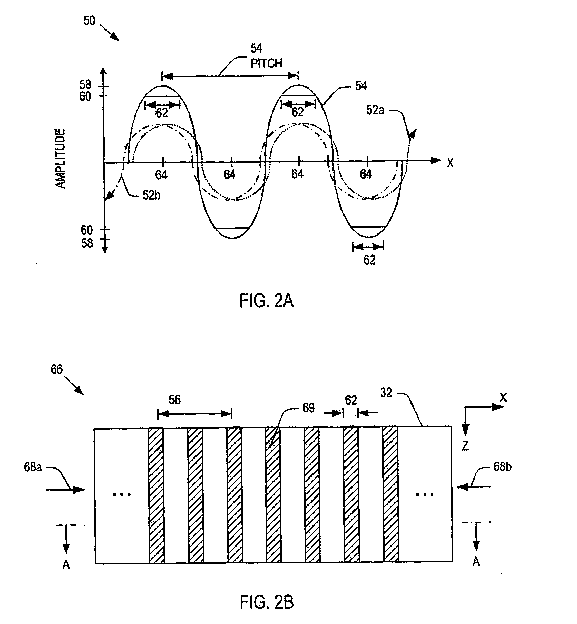
[0037] As mentioned, conventional microwave plasma systems generate a uniform power distribution within a microwave cavity by controlling phase differences between two microwaves transmitted to the microwave cavity. Unlike existing systems, the present invention provides methods and systems for controlling the phases of the microwaves so that they can generate stationary high-energy regions within microwave cavities. Also methods for configuring a plasma nozzle array so as to use power from the high-energy regions are disclosed.

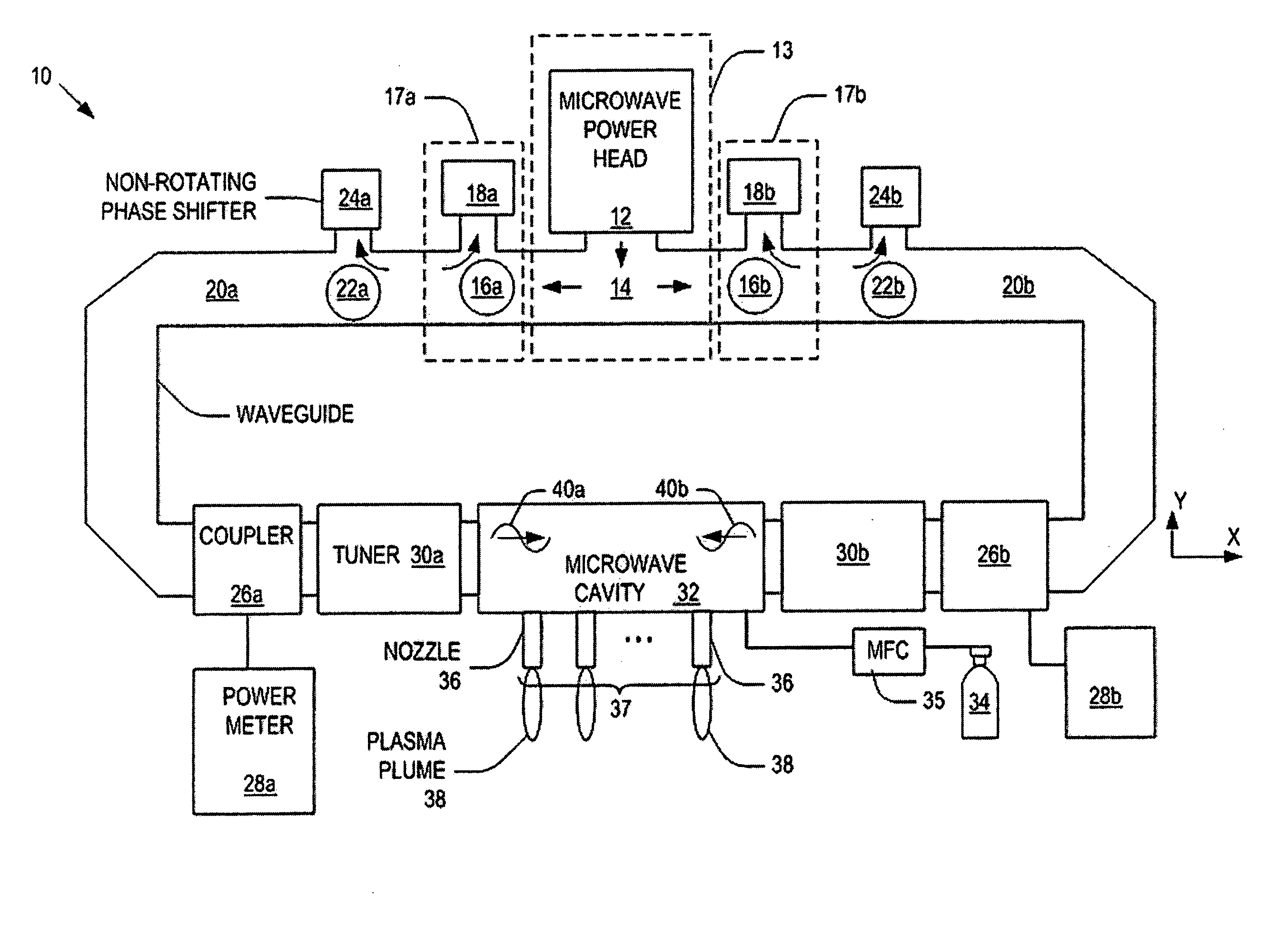
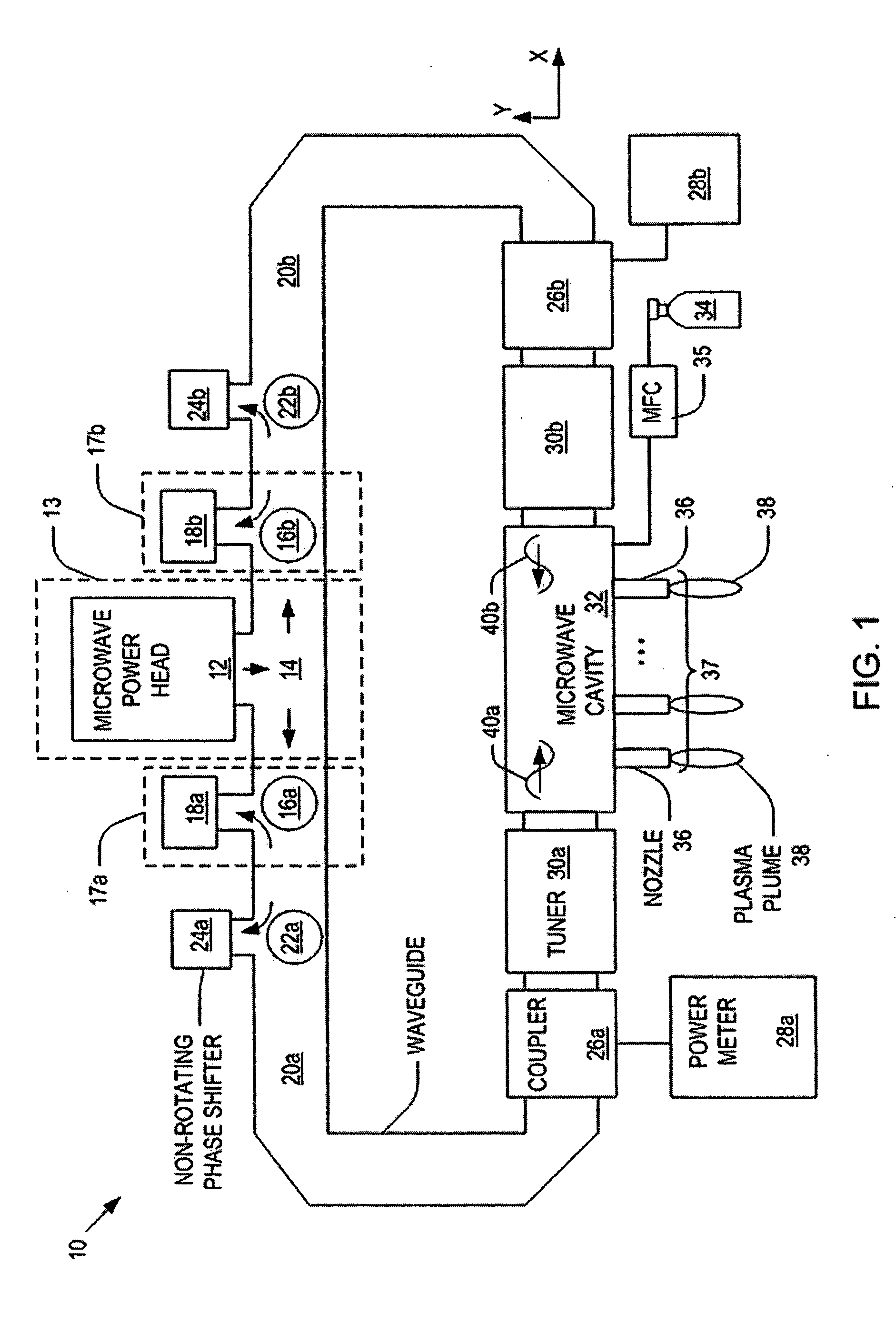
[0038]FIG. 1 is a schematic diagram of a system 10 having a plasma nozzle array in accordance with one embodiment of the present invention. As illustrated, the system 10 comprises: a microwave source 13 having a microwave power head 12 that generates microwaves and a power splitter 14 having two outlets that split the microwaves generated by the microwave power head 12; a pair of isolators 17a and 17b configured to dissipate retrogressing microwaves that tra...


PUM

PropertyMeasurementUnit
temperatureaaaaaaaaaa
phaseaaaaaaaaaa
microwave energyaaaaaaaaaa

Abstract

Microwave plasma nozzle array systems and methods for configuring the microwave plasma nozzle arrays are disclosed. The microwaves are transmitted to a microwave cavity in a specific manner and form an interference pattern that includes high-energy regions within the microwave cavity. The high-energy regions are controlled by the phases and the wavelengths of the microwaves. A plurality of nozzle elements is provided in the array. Each of the nozzle elements has a portion partially disposed in the microwave cavity and receives a gas for passing therethrough. The nozzle elements receive microwave energy from one of the high-energy regions. Each of the nozzle elements include a rod-shaped conductor having a tip that focuses the microwaves and a plasma is then generated using the received gas.

Description

CROSS REFERENCE TO RELATED APPLICATIONS [0001] This application is related to concurrently filed U.S. application Ser. No.______, filed on Jul. 30, 2004, entitled “SYSTEM AND METHOD FOR CONTROLLING A POWER DISTRIBUTION WITHIN A MICROWAVE CAVITY” which is hereby incorporated by reference in its entirety.BACKGROUND OF THE INVENTION [0002] 1. Field of the Invention [0003] The present invention relates to plasma generating systems, and more particularly to microwave plasma systems having plasma nozzle arrays. [0004] 2. Discussion of the Related Art [0005] In recent years, the progress on producing plasma has been increasing. Typically, plasma consists of positive charged ions, neutral species and electrons. In general, plasmas may be subdivided into two categories: thermal equilibrium and thermal non-equilibrium plasmas. Thermal equilibrium implies that the temperature of all species including positive charged ions, neutral species, and electrons, is the same. [0006] Plasmas may also be...

Claims


Application Information

Patent Timeline
Patent Type & Authority Applications(United States)
IPC IPC(8): B08B6/00C23C16/00
CPCA61L2/14H05H1/46H05H1/24H01J37/32192H05H1/4622H01J37/32229
Inventor LEE, SANG HUNKIM, JAY JOONGSOO
Owner NOXILIZER
Why Eureka
Try Eureka