Terahertz radiation source
A radiation source, Hertz wave technology, used in radiation sources, masers, discharge tubes, etc.
- Summary
- Abstract
- Description
- Claims
- Application Information
AI Technical Summary
Problems solved by technology
Method used
Image
Examples
Embodiment 1
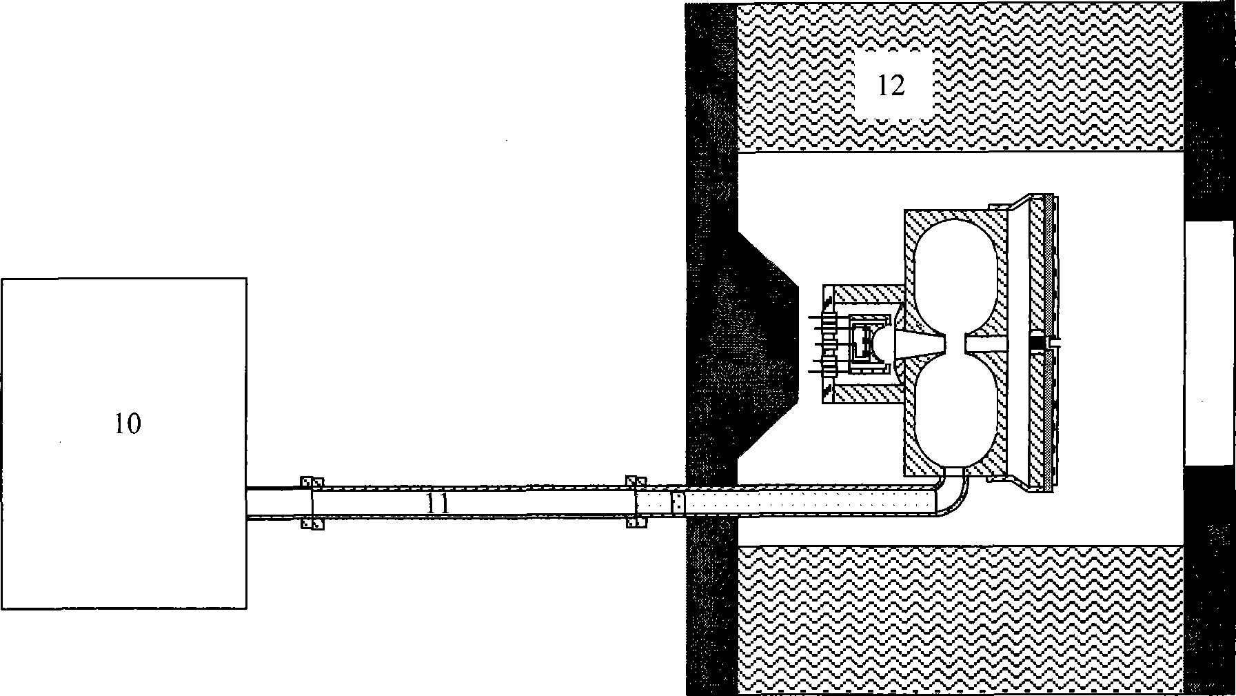
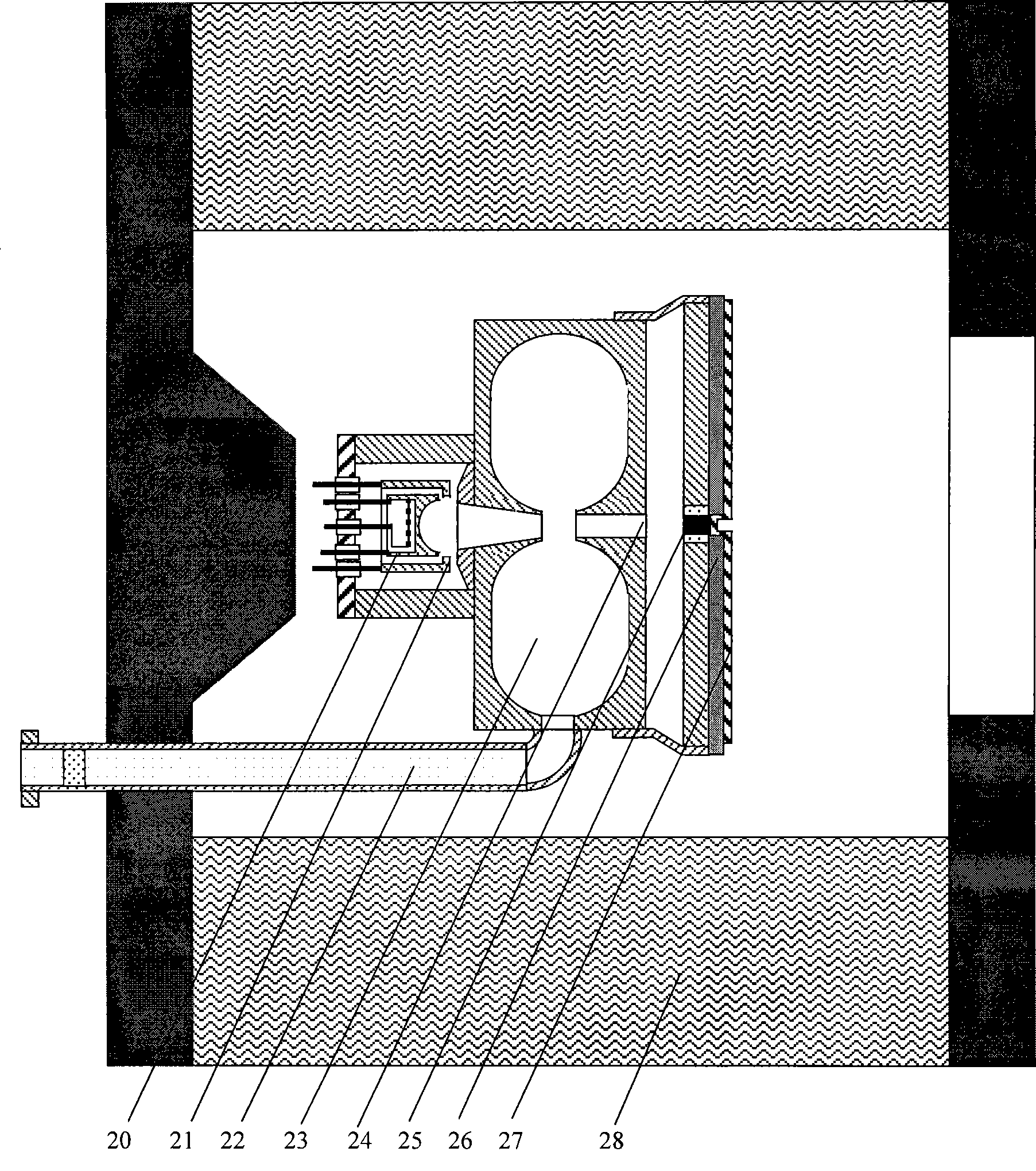
[0022]Embodiment 1: The output power of the microwave source is 1 watt, and the frequency is 30 GHz, which is input into the resonant cavity of the THz wave generator through the hollow metal waveguide. The cathode adopts an oxide hot cathode, and the potential of the focusing electrode is negative relative to the cathode. The microwave resonant cavity adopts a reentrant cavity structure and is made of oxygen-free copper. The electron beam drift cluster hole diameter is 0.4 mm, the nose cone spacing is 0.4 mm, and the drift tube length behind the nose cone is 3 mm. The film radiation antenna is made of titanium-gold composite film with a thickness of 300 nanometers. The dielectric layer in the thick film capacitor is polyimide with a thickness of 50 microns. A voltage of -1500 volts is applied to the cathode, the total current emitted by the cathode is 3 mA, and a voltage of -750 volts is applied to the antenna to obtain an average power of 300 milliwatts of THz wave radiati...
Embodiment 2
[0023] Embodiment 2: The power of the microwave source is 1 watt, the frequency is 30 GHz, and it is input into the resonant cavity of the THz wave generator through the coaxial line. The cathode adopts film-coated barium tungsten thermal cathode, and the potential of the focusing electrode is negative relative to the cathode. The microwave resonant cavity adopts a reentrant cavity structure and is made of oxygen-free copper. The electron beam drift cluster hole diameter is 0.4 mm, the nose cone spacing is 0.4 mm, and the drift tube length behind the nose cone is 4 mm. The film radiation antenna is made of titanium-gold composite film with a thickness of 300 nanometers. The dielectric layer in the thick film capacitor is polyimide with a thickness of 50 microns. A voltage of -1500 volts is applied to the cathode, the total current emitted by the cathode is 3 mA, and a voltage of -750 volts is applied to the antenna to obtain an average power of 300 milliwatts of THz wave rad...
Embodiment 3
[0024] Embodiment 3: The output power of the microwave source is 0.8 watts, and the frequency is 40 GHz, which is input into the resonant cavity of the THz wave generator through the hollow waveguide. The cathode adopts a micro-tip type field emission cold cathode, and the potential of the focusing electrode is negative relative to the cathode. The microwave resonant cavity adopts a reentrant cavity structure and is made of oxygen-free copper. The electron beam drift cluster hole diameter is 0.3 mm, the nose cone spacing is 0.3 mm, and the drift tube length behind the nose cone is 2.5 mm. The film radiation antenna is made of titanium-gold composite film with a thickness of 300 nanometers. The dielectric layer in the thick film capacitor is polyimide with a thickness of 40 microns. A voltage of -1500 volts is applied to the cathode, the total current emitted by the cathode is 2 mA, and a voltage of -750 volts is applied to the antenna to obtain an average power of THz wave r...
PUM
 Abstract
Description
Claims
Application Information
 - R&D
- Intellectual Property
- Life Sciences
- Materials
- Tech Scout
- Unparalleled Data Quality
- Higher Quality Content
- 60% Fewer Hallucinations
Browse by: Latest US Patents, China's latest patents, Technical Efficacy Thesaurus, Application Domain, Technology Topic, Popular Technical Reports.
© 2025 PatSnap. All rights reserved.Legal|Privacy policy|Modern Slavery Act Transparency Statement|Sitemap|About US| Contact US: help@patsnap.com


