
Method of and apparatus for in-situ measurement of changes in fluid composition by electron spin resonance (ESR) spectrometry

Active Publication Date: 2008-07-10
ACTIVE SPECTRUM
View PDF9 Cites 25 Cited by
  • Summary
  • Abstract
  • Description
  • Claims
  • Application Information

AI Technical Summary

Benefits of technology

[0016]An object of the present invention therefore is to provide an improved miniature electron spin resonance (ESR) sensor optimized for the in situ detection particularly, though not exclusively, of molecular peroxy radicals in engine oil and related or other machinery fluids caused by breakdown of lubricating (engine) oil, as indicated by a sharp increase in the concentration of damaging peroxy radicals (RO2.), among others, in the oil that are readily identified by electron spin resonance (ESR) spectroscopy and rise therein to a clear and direct indication of the engine oil condition.
[0018]A further object of this invention is to provide a novel compact and robust fluid condition sensor free from serious vibration and environmental effects and particularly suitable for sensing the presence of free radicals in fluids such as lubricants.
[0019]From the viewpoint of more specific improvements, other objects of this invention include measurement of the direct presence of free radicals using electron spin resonance wherein novel magnetic circuits yield a very spatially uniform magnetic field with minimal fringing through the sample sensing region—this, within a high Q miniature microwave cavity structure having fluid inlet and outlet ports for passing a fluid sample through the cavity structure. A uniform but modulated magnetic field passes through the cavity, wherein the fluid sample volume is maximized within a magnetic region of the cavity structure to increase the instrument sensitivity.

Problems solved by technology

In the case of engine coolant, increased acidity leads to corrosion in internal engine components.
There are to date, however, no commercially-available sensors that provide a rigorous, real-time detection of the most fundamental chemical mechanism of engine lubricating oil failure,—the formation of free radicals by the breakdown of long hydrocarbon molecular chains in oil.
The net economic benefit of this optimized maintenance schedule can be very large.

Method used


Image

  • Method of and apparatus for in-situ measurement of changes in fluid composition by electron spin resonance (ESR) spectrometry
  • Method of and apparatus for in-situ measurement of changes in fluid composition by electron spin resonance (ESR) spectrometry
  • Method of and apparatus for in-situ measurement of changes in fluid composition by electron spin resonance (ESR) spectrometry

Examples


Embodiment Construction

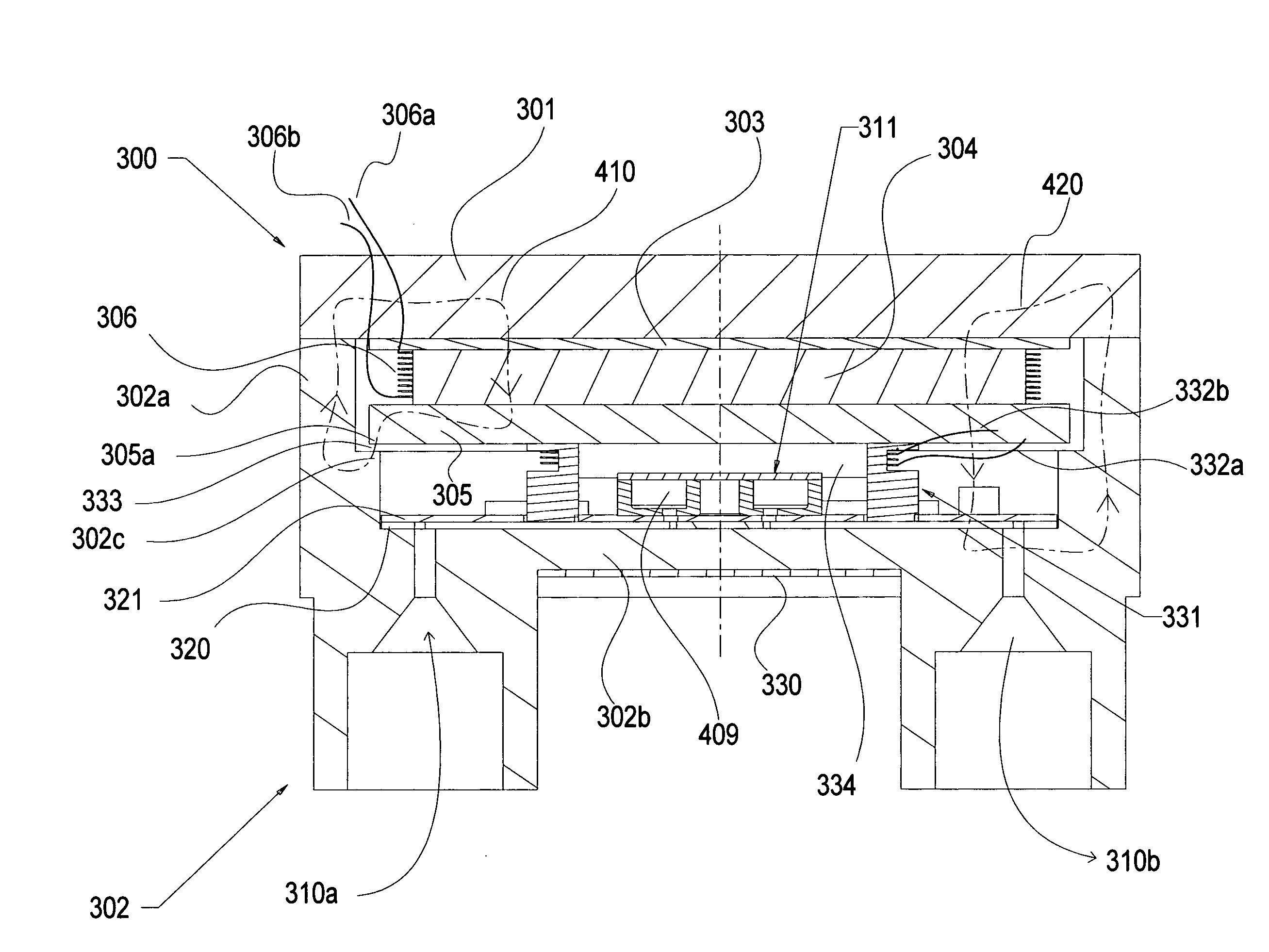
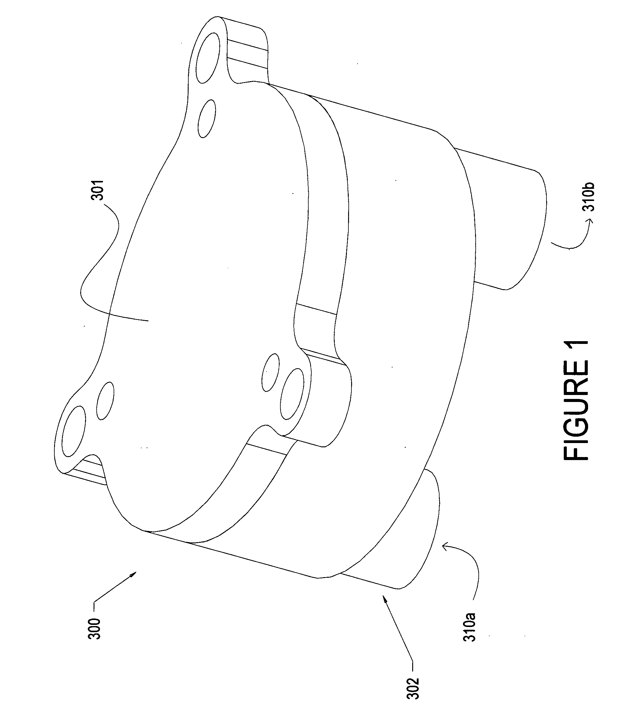
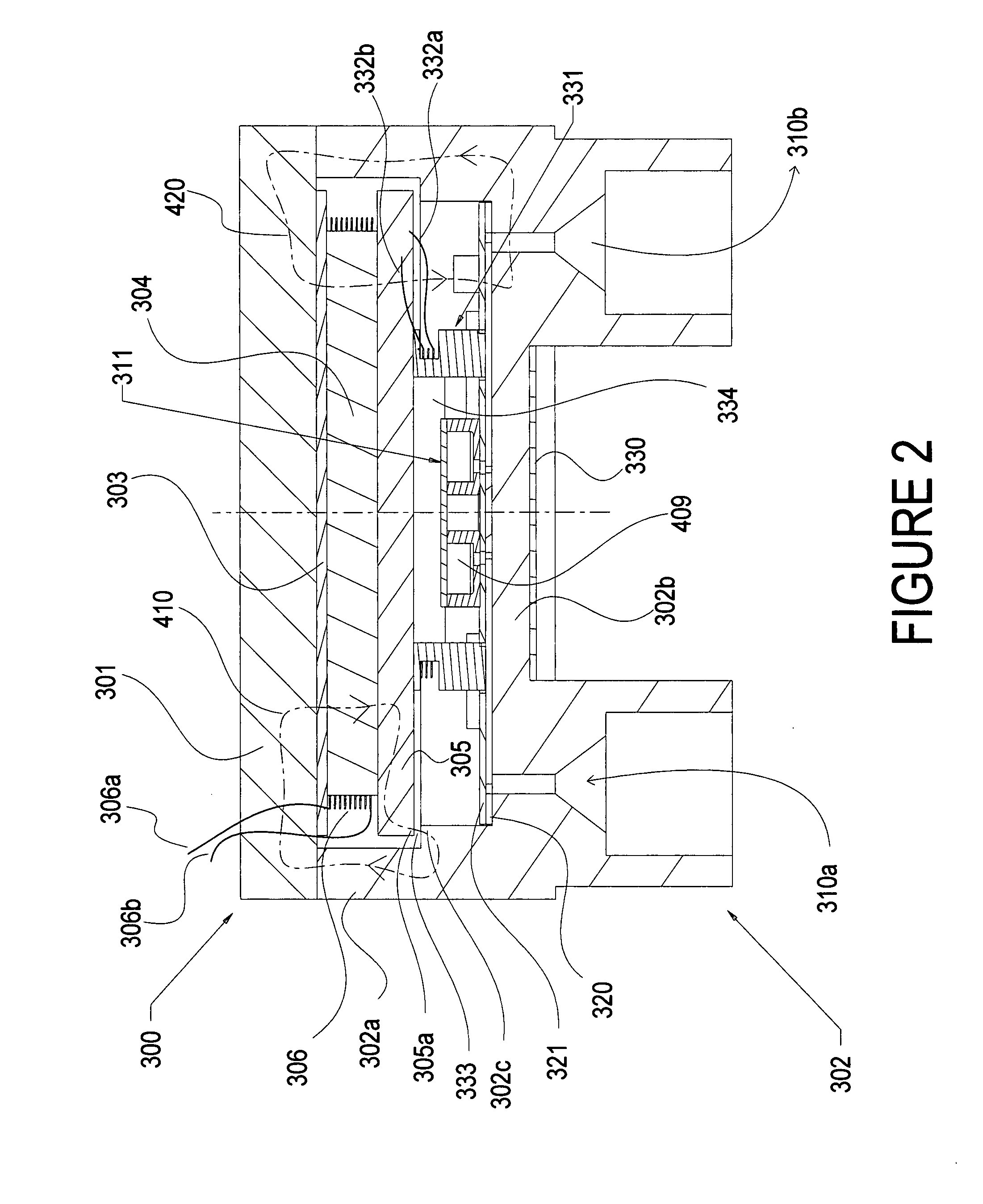
[0040]FIGS. 1 and 2 show the sensor 300 of this continuation-in-part invention, with its encasing structure 302, with a bottom 302b, cylindrical sides 302a and a top wall 301. Top 301 has attached to it, for example by bonding, a non-magnetic shim such as a brass shim 303, FIG. 2, to which is then bonded axially poled cylindrical magnet 304 and pole piece 305. Coil 306, with leads 306a and 306b, circumferentially surrounds the magnet 304. As current is applied to the coil leads, the generated magnetic field interacts with the filed of the permanent magnet to slowly vary the net magnetic field that travels uniformly through the system. The first magnetic field path 410 (shown in the dash-line left-side loop in FIG. 2) travels axially into pole piece 305 and then radially out to the perimeter 305a of the pole piece. The field lines cross the gap 333 and cross into the step feature 302c of the cavity sidewall 302a. This small overlap region causes the field to saturate inside the metal...


PUM


Abstract

A miniaturized instrument and method of using electron spin resonance spectrometry for measuring the degradation of lubricating fluids, and the like, that includes continuously passing a sample of such fluid through a resonating RF microwave cavity resonator during the application therethrough of a uniform slowly varying uniform magnetic field that is rapidly modulated and measuring the resulting phase modulation or amplitude modulation thereof to derive an electron spin resonance signal that directly senses the molecular changes in the fluid sample resulting from fluid degradation during operation of the vehicle, such as peroxy radicals in vehicle engine oil and the like.

Description

STATEMENT REGARDING FEDERALLY FUNDED RESEARCH[0001]Federal funds were used in the development of the cavity structure improvements underlying this invention under Contract No. W56 HZV-06-C-0582 awarded by the U.S. Army, this application being a continuation-in-part of parent U.S. application Ser. No. 11 / 590,522, filed Oct. 31, 2006 for Method Of And Apparatus For In-Situ Measurement Of Degradation Of Automotive Fluids And The Like by Micro-Electron Spin Resistance (ESR) Spectrometry.FIELD OF THE INVENTION[0002]The invention relates to the field of electron spin resonance (ESR) spectrometry, and more particularly to the use of such technology for measuring and diagnosing the real-time degradation or changes in fluid composition during use in operating, machinery such as of automotive engine oil and the like, in situ and during operating engine conditions and environments, as more particularly described in said parent application.BACKGROUND OF THE INVENTION[0003]As explained in said p...

Claims


Application Information

Patent Timeline
IPC IPC(8): G01N24/10
CPCG01N24/08G01N24/10G01R33/307H01P7/06G01R33/343G01R33/345G01R33/60G01R33/34
Inventor WHITE, JAMESWHITE, CHRISTOPHER
Owner ACTIVE SPECTRUM
Learn More