Device and method for optical imaging of retinal function

a retinal function and optical imaging technology, applied in the field of retinal neuronal activity imaging, can solve the problems of difficult monitoring changes, perimetry is relatively insensitive to early detection, optic nerve damage, etc., and achieve the effect of increasing the signal-to-noise ratio (snr) and increasing the sensitivity of the instrumen

Inactive Publication Date: 2006-10-10
IOWA RES FOUND UNIV OF +2
View PDF18 Cites 47 Cited by
  • Summary
  • Abstract
  • Description
  • Claims
  • Application Information

AI Technical Summary

Benefits of technology

[0012]In addition, the present invention can have a field of view of 45 degrees with 1000 pixels, or 0.5 degree-spatial resolution when a 12×12 pixel region is used for spatial averaging. This is an improvement over the spatial resolution of 1–2 degrees for the multifocal ERG. The system of the present invention can obtain functional signals rapidly (approximately 10 seconds for each iteration of stimulus response), so that there is ample opportunity to increase the signal-to-noise ratio (SNR) with multiple iterations, and thus increase the sensitivity of the instrument. Such a functional map of ganglion cell activity provides a means to detect a regional defect caused by glaucoma at an early stage, before visual perception or structural abnormalities become apparent.

Problems solved by technology

Also, a high percentage (approximately 40–50%) of the optic nerve may be damaged before a significant perceptual change can be detected on the visual field test, making perimetry relatively insensitive for detecting early damage when intervention may still save vision.
Further, the visual field test is highly variable in areas of defects where damage has occurred, making it difficult to monitor changes.

Method used


Image

  • Device and method for optical imaging of retinal function
  • Device and method for optical imaging of retinal function
  • Device and method for optical imaging of retinal function

Examples


Embodiment Construction

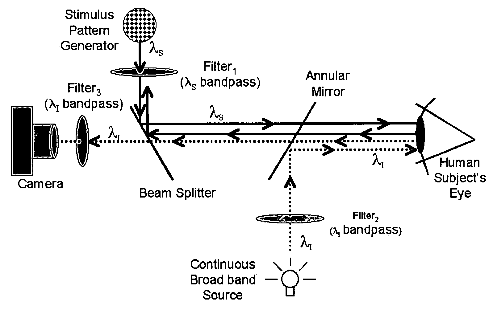
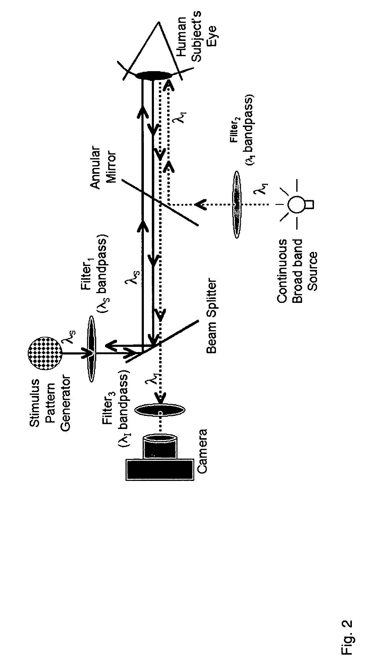
[0037]The optical recording of intrinsic neuronal signals is suited for objective assessment of retinal function. Like the cortex, neuronal signals from the retina can be recorded from a large area at once with high spatial resolution. Unlike cortex imaging, retinal imaging can be acquired directly through a dilated pupil or other area of the eye using an appropriate fundus imaging system. Optical recording of retinal function is noninvasive and ideal for clinical application.

[0038]Optical functional recording is possible in the retina because the retina is a direct extension of the brain and part of the central nervous system. Neuronal activity of the retina is fundamentally similar to that of the brain. Like the brain, appropriate metabolic changes (changes in hemoglobin oxygen saturation and state of tissue cytochrome for example) can be detected in the retina in response to changes in inspired oxygen levels.

[0039]The following steps are included in a preferred embodiment of an i...


PUM


Abstract

An Optical Imaging Device of Retinal Function has been developed to detect changes in reflectance of near infrared light from the retina of human subjects in response to visual activation of the retina by a pattern stimulus. The measured changes in reflectance correspond in time to the onset and offset of the visual stimulus in the portion of the retina being stimulated. Any changes in reflectance can be measured by interrogating the retina with a light source. The light source may be presented to the retina via the cornea and pupil or through other tissues in and around the eye. Different wavelengths of interrogating light may be used to interrogate various layers of the retina. Additionally, various novel patterns and methods of stimulation have been developed for use with the imaging device and methods.

Description

CROSS-REFERENCE TO RELATED APPLICATION[0001]The benefit of the filing date of U.S. Provisional Patent Application Ser. No. 60 / 349,435, filed Jan. 18, 2002, entitled “OPTICAL IMAGING DEVICE OF RETINA FUNCTION,” is hereby claimed, and the specification thereof incorporated herein in its entirety.ACKNOWLEDGMENT[0002]This invention was made with government support under Grant number 1R43EY12915-01A1 awarded by the National Eye Institute. The government has certain rights in the invention.FIELD OF THE INVENTION[0003]The invention relates in general to retinal neuronal activity imaging. More particularly, the invention relates to instrumentation and methodologies in the diagnostic imaging of stimulus responsive ocular fundus neuronal activity.BACKGROUND OF THE INVENTION[0004]The current standard for detecting and monitoring progression of diseases of the optic nerve (i.e. glaucoma, ischemic optic neuropathy, compressive optic neuropathy) and retina is visual field testing (perimetry). Per...

Claims


Application Information

Patent Timeline
Patent Type & Authority Patents(United States)
IPC IPC(8): A61B3/14A61B3/10A61B3/12A61B5/00
CPCA61B3/0058A61B3/12A61B5/14555
Inventor KARDON, RANDY H.KWON, YOUNG H.TSO, DANIELSOLIZ, PETER
Owner IOWA RES FOUND UNIV OF
Why Eureka
Try Eureka