Microwave cavity sensor

a cavity sensor and microwave technology, applied in the direction of instruments, nuclear magnetic resonance analysis, reradiation, etc., can solve the problems of corrosion monitoring, metal corrosion, and limited space available for multiphase meters in off shore christmas tree production systems

Active Publication Date: 2015-04-09
HERIOT WATT UNIV
View PDF3 Cites 24 Cited by
  • Summary
  • Abstract
  • Description
  • Claims
  • Application Information

AI Technical Summary

Problems solved by technology

The space available for a multiphase meter in an off shore Christmas tree production system is limited.
Corrosion monitoring is another significant problem, particularly in the oil and gas industry.
The aggressive influence of acids, alkaline solutions and gases cause corrosion in metals.
Corrosion in plastics is caused due to the capture of foreign particles, UV light and heat.
They fail to detect deterioration in paint or protective coating materials and the conditions responsible for the onset of corrosion.
Non-Destructive Testing (NDT) techniques such as ultrasonics, radiography, thermography and eddy current measurement techniques are not sensitive enough for corrosion prognostics.
Therefore, these methods are unsuitable for detecting and evaluating properties (i.e. presence and thickness) of corrosion layers under thin layers of paint and primer.
Corrosion of metal is a complex problem and its effect on commercial and industrial equipment is immense for the safety and integrity of a large array of assets.
However, the sensor cannot detect dielectric or material properties, and so cannot detect changes in these properties.
In addition, data collected from the reservoirs can be sparse and expensive to obtain.
Many EPR spectroscopy systems have difficulty with automatic frequency control (AFC) locking to a low Q resonator.
Difficulty in obtaining an AFC lock may cause frequency drift, error voltage, dispersion and noise.

Method used


Image

  • Microwave cavity sensor
  • Microwave cavity sensor
  • Microwave cavity sensor

Examples


Embodiment Construction

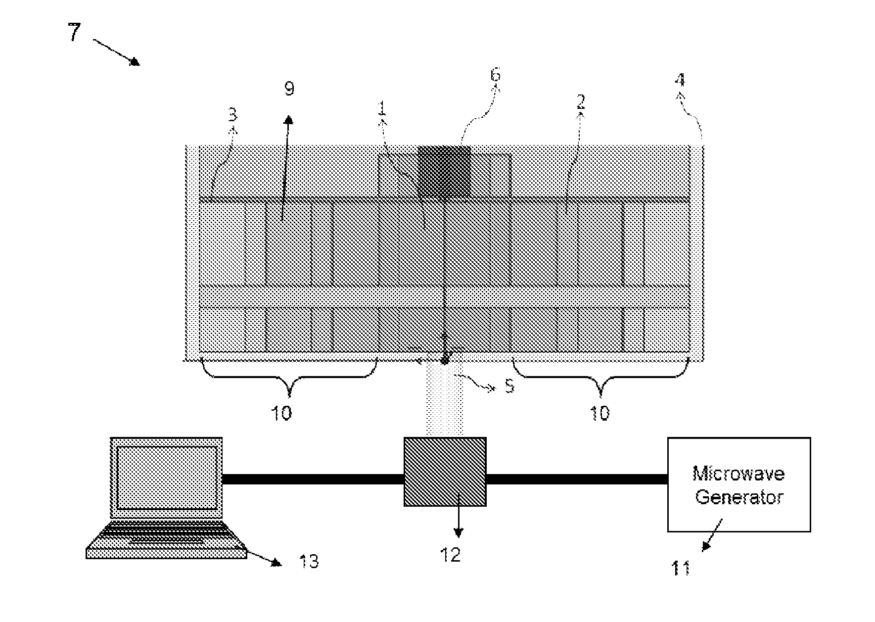
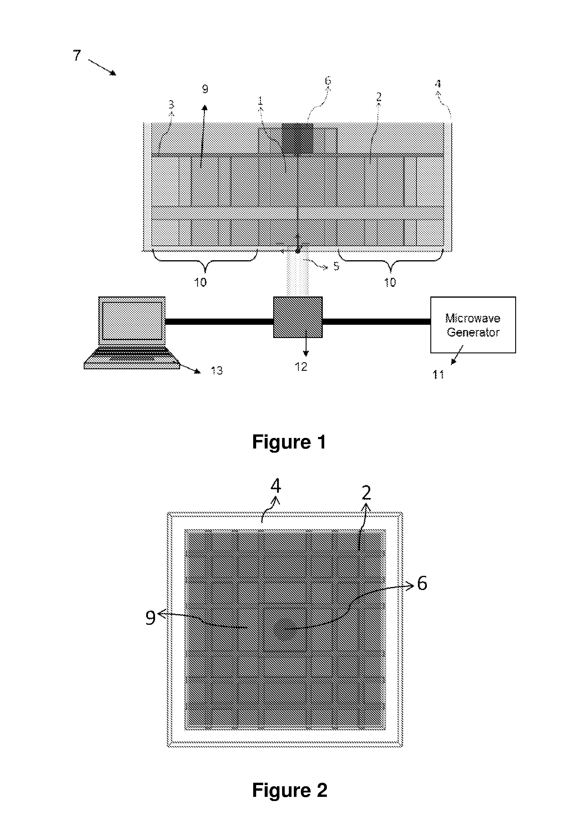
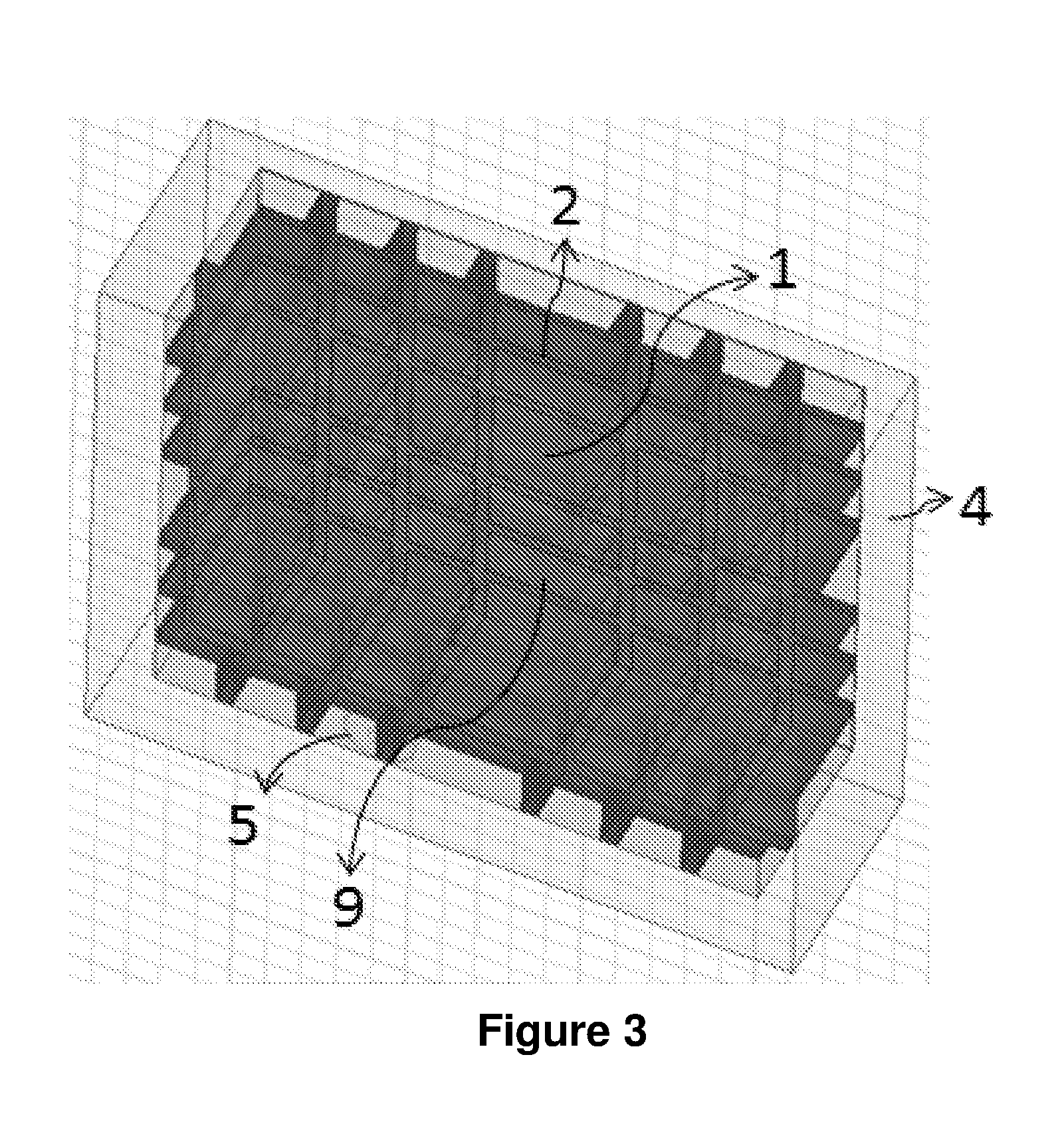
[0033]FIG. 1 shows a cross section of a high Q Bragg reflector based open ended microwave resonator sensor 7. The sensor 7 is dielectric structure having a waveguide 1 and a concentrator 10 surrounding the waveguide 1. One end of the waveguide is connected to a microwave generator 11 via a SMA connector 5, so that microwaves can be injected along a longitudinal axis of the waveguide. The opposite end along the longitudinal axis of the waveguide is terminated with a dielectric reflector 3 of defined thickness. The waveguide 1 extends beyond the dielectric reflector to form a sample chamber 6. The waveguide 1 has a resonant wavelength of half the excitation wavelength λ / 2. The dielectric reflector has a thickness of at least λg / 20 where λg is the wavelength of the excited electromagnetic wave in the dielectric. The function of the dielectric reflector is to maximise electromagnetic field intensity in the sample chamber 6. In practice, the dielectric reflector should be made of a diele...


PUM

PropertyMeasurementUnit
distanceaaaaaaaaaa
relative dielectric constantaaaaaaaaaa

Abstract

A sensor comprising: a dielectric waveguide for guiding a microwave signal; and a dielectric reflector at an end of the dielectric waveguide to cause formation of a sensing field beyond an outer surface of the dielectric reflector.

Description

INTRODUCTION[0001]The present invention relates to a microwave cavity sensor. The microwave cavity sensor of the invention is particularly useful for the detection of the composition of a multiphase mixture, the measurement of corrosion and the determination of the chemistry of dielectric materials, the latter when used in conjunction with Electron Paramagnetic Resonance (EPR) and Nuclear Magnetic Resonance (NMR).BACKGROUND[0002]Monitoring of pipes and canalisations in the oil and gas industry requires a large number of measurements to be performed in order to control or prevent the development of scale and corrosion or for managing and monitoring a fluid flow when the fluid has to be transported a long distance in a pipeline. The composition and the flow rates of individual components of a mixture of oil and water and possibly gas fluid flowing in a pipe need to be monitored. These measurements are needed to determine the constituents present in the oil well and also to help contro...

Claims


Application Information

Patent Timeline
Patent Type & Authority Applications(United States)
IPC IPC(8): G01N22/00G01N24/08
CPCG01N24/08G01N22/00
Inventor DESMULLIEZ, MARCPAVULURI, SUMANTH KUMARFLYNN, DAVIDHERD, DAVID
Owner HERIOT WATT UNIV
Why Eureka
Try Eureka