Thickness measuring apparatus and method using a microwave cavity resonator

a cavity resonator and thickness measurement technology, applied in the field of measurement, can solve the problems of prohibitive process difficulty, undesirable cycle delay, difficult to measure materials using conventional techniques, etc., and achieve the effect of low direct-current conductivity and magnetic permeability

Inactive Publication Date: 2007-02-06
THE BOEING CO
View PDF6 Cites 27 Cited by
  • Summary
  • Abstract
  • Description
  • Claims
  • Application Information

AI Technical Summary

Benefits of technology

[0009]The foregoing needs are met, to a great extent, by the present invention, wherein in one aspect an apparatus is provided that in some embodiments can be c...

Problems solved by technology

These materials are difficult to measure using conventional techniques since they have relatively low direct-current conductivity and magnetic permeability.
This can result in an undesirable cycle delay of, for example, up to three hours.
However, this process can be prohibitively difficult in the case of large components, for example, an airplane fuselage.
Since an acceptably accurate and dependable direct measurement technology for composite materials is not available, when the primer film is suspected of being excessively thick or uneven, the component typically must be disassembled and repainted at significant cost and risk of damag...

Method used


Image

  • Thickness measuring apparatus and method using a microwave cavity resonator
  • Thickness measuring apparatus and method using a microwave cavity resonator
  • Thickness measuring apparatus and method using a microwave cavity resonator

Examples


Embodiment Construction

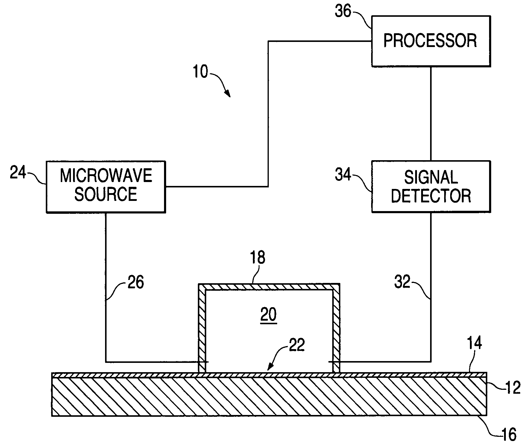
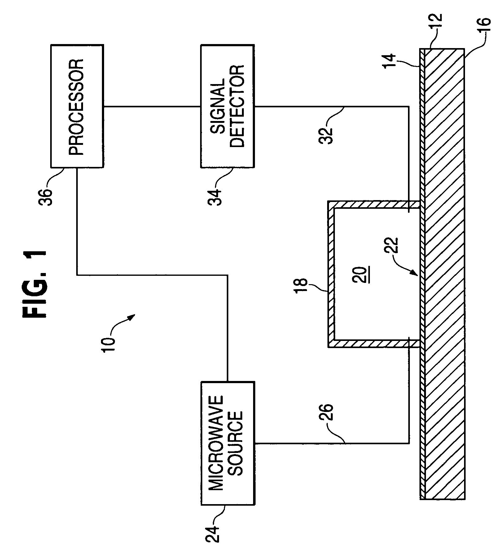
[0022]An embodiment in accordance with the present invention provides a portable and accurate measurement device for measurement of a thin film thickness over a substrate that has relatively low direct-current conductivity and magnetic permeability. The measurement device can include a resonant cavity with an open side. The resonant cavity can include a chamber that has a predetermined electromagnetic resonant frequency in the microwave range when the open side is placed against the surface of a conductive material, which can act as a wall of the resonant cavity.

[0023]The measurement device can also include a microwave source that can produce an electromagnetic wave signal in the super high frequency range, for example, between three and thirty gigahertz (GHz), which can be introduced into the resonant cavity at one end, or side. For example, the device can include a monolithic microwave integrated circuit (MMIC) voltage-controlled oscillator (VCO) with a variable output frequency, ...


PUM


Abstract

A measurement device for measuring a thickness of a film layer over a substrate utilizes a microwave source and a resonant cavity having an open side. A microwave signal is introduced at a first end of the resonant cavity with the open side against a surface measurement sample having a film layer over a substrate, and an output signal detector senses the output power of the signal at a far end of the resonant cavity. A processor uses a difference in the resulting resonant frequency of the cavity from that using a substrate without the film layer to determine the thickness of the film layer.

Description

FIELD OF THE INVENTION[0001]The present invention relates generally to the field of measurements. More particularly, the present invention relates to nondestructive measurement of the thickness of a dielectric film over a radiopaque substrate using electromagnetic cavity resonance principles.BACKGROUND OF THE INVENTION[0002]Nondestructive measurement of a film thickness is an important objective for many industries. For example, in the aircraft industry, paint for functional and decorative purposes is often applied to aircraft surfaces, which may have near critical weight. Also, prior to applying a surface paint, care must be taken to ensure that an adequate amount of primer is uniformly applied with an adequate thickness to act as a proper corrosion inhibitor. For example, in some aircraft applications, a paint film thickness of 0.4 to 1.0 thousandth of an inch (mil) over the surface of the substrate is desirable. Moreover, depending on the model of aircraft, over 500 pounds of pri...

Claims


Application Information

Patent Timeline
IPC IPC(8): G01R27/04
CPCG01B15/02
Inventor FAY, CHRISTOPHER WMONK, ANTHONY DOLMSTED, CLIFFORD CSERGOYAN, EDWARD G
Owner THE BOEING CO
Why Eureka
Try Eureka