
Systems and methods for magnetic shielding for a superconducting computing system

Active Publication Date: 2019-06-13
D-WAVE SYSTEMS
View PDF0 Cites 2 Cited by
  • Summary
  • Abstract
  • Description
  • Claims
  • Application Information

AI Technical Summary

Benefits of technology

The patent describes a magnetic shielding system for a superconducting computing system. The system includes multiple shields and a shield cap that work together to minimize magnetic interference. The shields have varying thickness and magnetic permeability to handle larger problems. The system also includes a inner shielding layer and a fourth shield to further enhance magnetic shielding. The technical effects of the system include improved performance and reliability of the superconducting computing system and reduced interference between components.

Problems solved by technology

Magnetic fields produced by external sources may cause unwanted interactions with devices in the integrated circuit.
The quantum properties of quantum devices are very sensitive to noise, and stray magnetic fields in superconducting quantum devices can negatively impact the quantum information processing properties of such circuits.
However, Burk and Ekstrom (2002) found that shield cap geometry does not contribute significantly to shielding longitudinal fields in comparison to other considerations such as shield geometry and spacing between shield layers.
However, such shields can be costly or difficult to manufacture.
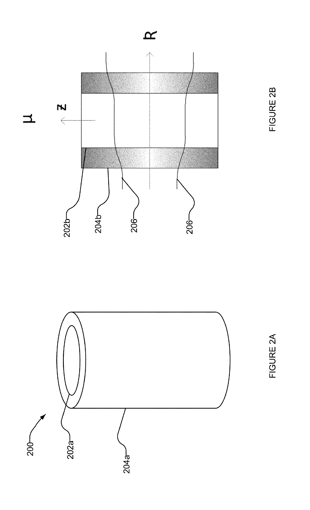
Uniform cylindrical shields with a constant permeability and thickness, even if arranged concentrically, are typically ineffective at redirecting flux lines in the axial direction.
Other limitations of the related art will become apparent to those of skill in the art upon a reading of the specification and a study of the drawings.

Method used


Image

  • Systems and methods for magnetic shielding for a superconducting computing system
  • Systems and methods for magnetic shielding for a superconducting computing system
  • Systems and methods for magnetic shielding for a superconducting computing system

Examples


Embodiment Construction

[0039]In the following description, certain specific details are set forth in order to provide a thorough understanding of various disclosed implementations. However, one skilled in the relevant art will recognize that implementations may be practiced without one or more of these specific details, or with other methods, components, materials, etc. In other instances, well-known structures associated with computer systems, server computers, and / or communications networks have not been shown or described in detail to avoid unnecessarily obscuring descriptions of the implementations.

[0040]Unless the context requires otherwise, throughout the specification and claims that follow, the word “comprising” is synonymous with “including,” and is inclusive or open-ended (i.e., does not exclude additional, unrecited elements or method acts).

[0041]Reference throughout this specification to “one implementation” or “an implementation” means that a particular feature, structure or characteristic de...


PUM


Abstract

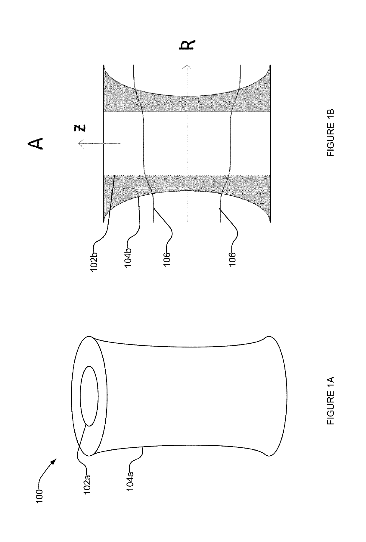
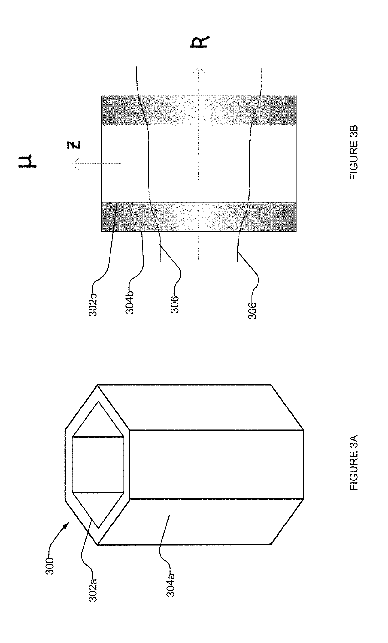
A magnetic shielding system that includes a shield that is non-uniform in the axial direction and a shield cap that is non-uniform in the radial direction. Each shield in the system may have a magnetic permeability, thickness, and / or radius that varies in the axial direction to create low-reluctance paths that redirect flux away from a sample towards the ends of the shield. Each shield cap in the system may have a magnetic permeability and / or thickness that varies in the radial direction to create low-reluctance paths that redirect flux away from the sample towards shield walls. An inner shielding layer formed from a material of low permeability and moderate-to-high coercivity may be implemented as the innermost layer of a magnetic shielding system.

Description

FIELD[0001]This disclosure generally relates to magnetic shielding systems and particularly relates to providing a low magnetic field environment for a superconducting computing system by creating a low reluctance path around a region where a superconducting processor is positioned.BACKGROUND[0002]Quantum Processor[0003]A computer processor may take the form of an analog processor, for instance a quantum processor such as a superconducting quantum processor. A superconducting quantum processor may include a number of qubits and associated local bias devices, for instance two or more superconducting qubits. Further detail and embodiments of exemplary quantum processors that may be used in conjunction with the present systems, methods, and apparatus are described in at least U.S. Pat. Nos. 7,533,068, 8,195,596, 8,190,548, and U.S. Patent Application No. 2011-0022820.[0004]A superconducting quantum processor may include a number of coupling devices operable to selectively couple respec...

Claims


Application Information

Patent Timeline
IPC IPC(8): H05K9/00G06N10/00H01L27/18G01R33/035
CPCH05K9/0077G06N10/00H01L27/18G01R33/0358B82Y10/00G01R33/035Y10S505/872H10N69/00
Inventor STERLING, GEORGE E.G.PEREGRYM, GREGORY D.KAN, EDMOND HO YIN
Owner D-WAVE SYSTEMS
Learn More