Fuel injection system

a fuel injection system and fuel pressure technology, applied in the direction of fuel injection apparatus, charge feed system, wear-reducing fuel injection, etc., can solve the problems of inability to compensate for axial tolerance, inability to manufacture gaskets, and insufficient gaskets for higher fuel pressures. achieve the effect of simple manner

Inactive Publication Date: 2006-02-02
ROBERT BOSCH GMBH
View PDF8 Cites 13 Cited by
  • Summary
  • Abstract
  • Description
  • Claims
  • Application Information

AI Technical Summary

Benefits of technology

[0003] The fuel injection system according to the present invention has the advantage over the related art that the assembly of the fuel injection system may take place in a considerably simpler manner because, due to the elastic axial expansibility of the gasket, the supply line segment may be attached to the cylinder head w...

Problems solved by technology

The disadvantage of the fuel injection system known from the above-mentioned publication is in particular that the gasket is inadequate for higher fuel pressures.
Furthermore, the radial gasket is incapable of compensating for axial tolerances which appear, for example, in op...

Method used


Image

  • Fuel injection system
  • Fuel injection system
  • Fuel injection system

Examples


Embodiment Construction

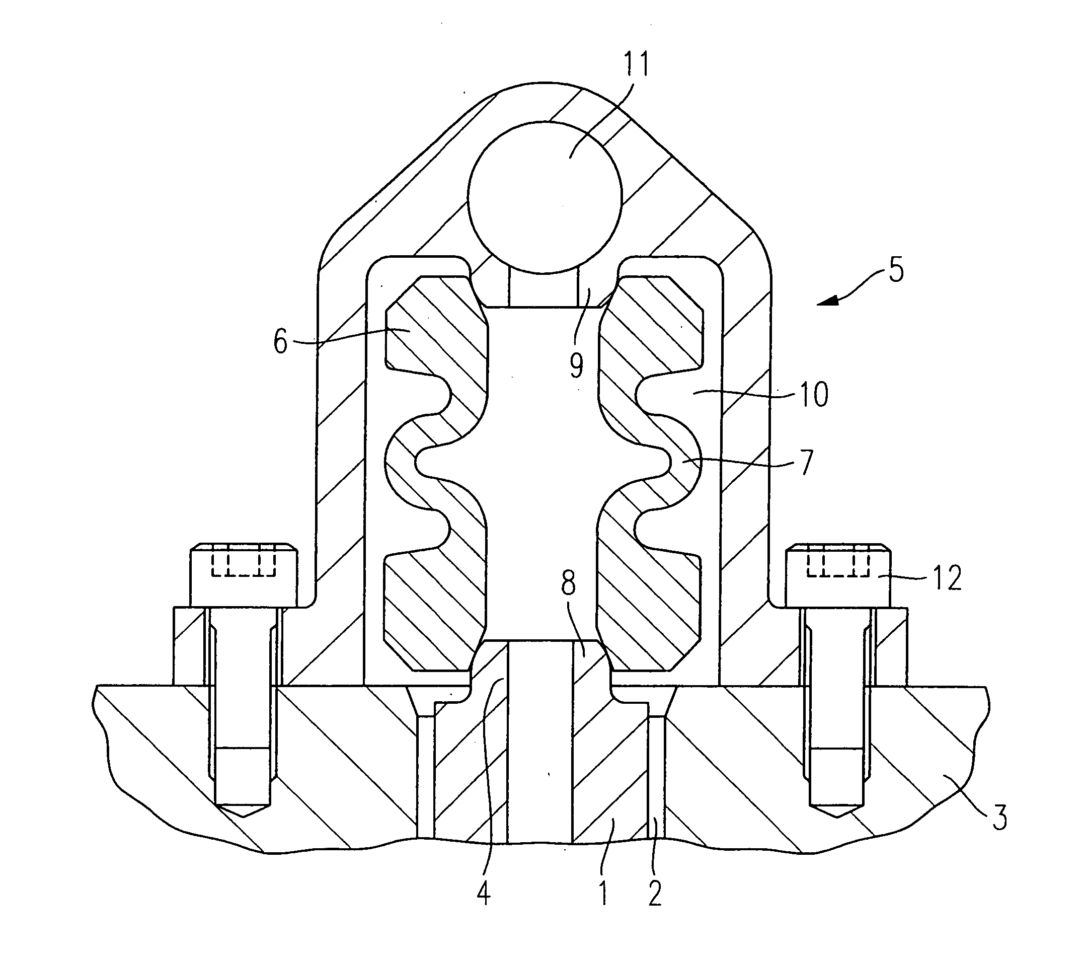
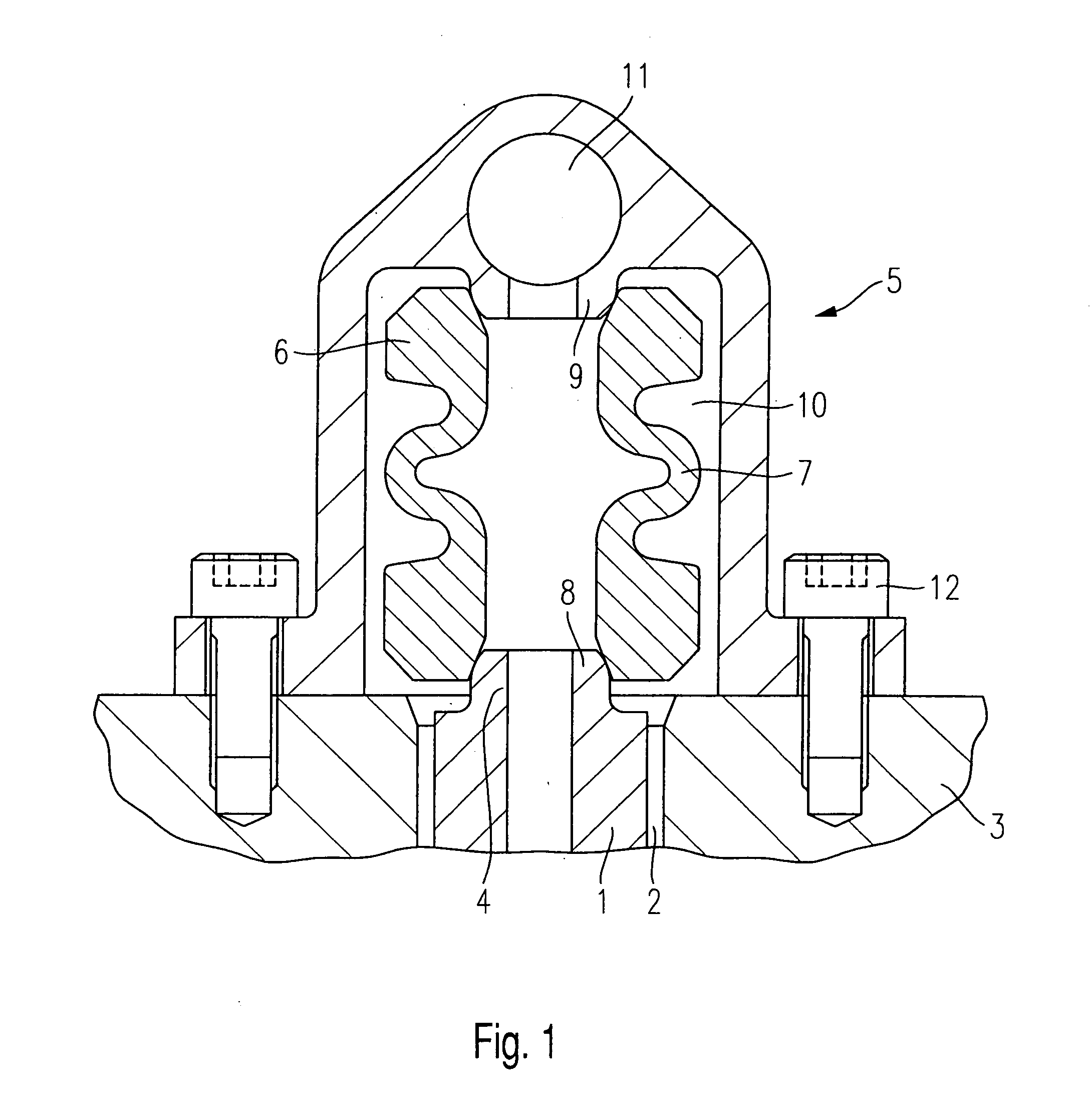
[0016] An exemplary embodiment of the fuel injection system according to the present invention, illustrated in FIG. 1, is designed here as a fuel injection system for supplying fuel and holding down fuel injectors for direct-injection internal combustion engines which may be self-igniting or externally ignited.

[0017] The fuel injection system according to the present invention schematically illustrated as an example essentially has a supply line segment 5, a fuel injector 1, and a gasket 6 elastically and pressure-tightly connecting supply line segment 5 to fuel injector 1. In this exemplary embodiment, almost the entire length of fuel injector 1 is situated in a receptacle bore hole 2 of cylinder head 3. On the inlet side, fuel injector 1 has a connecting piece 4, through which fuel is supplied under pressure to fuel injector 1. Connecting piece 4 projects slightly out from receptacle bore hole 2.

[0018] Supply line segment 5 is part of a fuel rail and, for each fuel injector 1, i...


PUM


Abstract

A fuel injection system, in particular for direct injection of fuel into the combustion chamber of an internal combustion engine has a plurality of fuel injectors, whose injection ends, at least, are situated in receptacle bore holes of a cylinder head. The inlet side of the fuel injectors has a connecting piece, which engages with a supply line segment. Pressurized fuel is supplied to the fuel injector via the supply line segment. The connecting piece is sealed off from the supply line segment by a gasket. The gasket has a sleeve-shaped design and has a plastically deformable shaped area, which is plastically deformed during the assembly of the supply line segment with the connecting piece, and has elastic properties while in operation.

Description

BACKGROUND INFORMATION [0001] German Patent Application No. DE 101 08 467, for example, describes a fuel injector which is supplied with fuel via a fuel distribution line. The injection end of the fuel injector is inserted into a receptacle opening of a cylinder head. The inlet end of the fuel injector projects into a receptacle opening of the fuel distribution line and is radially surrounded by an annular gasket, which seals off the fuel injector from the fuel distribution line. The gasket is designed as an O-ring and is made of a rubber-type material. [0002] The disadvantage of the fuel injection system known from the above-mentioned publication is in particular that the gasket is inadequate for higher fuel pressures. Furthermore, the radial gasket is incapable of compensating for axial tolerances which appear, for example, in operation due to different degrees of thermal expansion of the fuel distribution line and the cylinder head because of the inclination of the fuel injectors...

Claims


Application Information

Patent Timeline
IPC IPC(8): F02M55/02
CPCF02M55/004F02M69/465F02M2200/02F02M2200/9038F02M2200/16F02M2200/8053F02M2200/03
Inventor SCHMIEDER, DIETMAR
Owner ROBERT BOSCH GMBH
Why Eureka
Try Eureka