Impact damper assembly for an automobile

a technology for automobiles and dampers, applied in the direction of bumpers, vehicle components, pedestrian/occupant safety arrangements, etc., can solve the problem of keeping repair costs low, achieve the effect of reducing damage to the vehicle chassis, improving the overall vehicle safety, and being convenient to install

Inactive Publication Date: 2006-02-02
ZF FRIEDRICHSHAFEN AG
View PDF14 Cites 42 Cited by
  • Summary
  • Abstract
  • Description
  • Claims
  • Application Information

AI Technical Summary

Benefits of technology

[0012] According to advantageous embodiment, the additional conical stiffening elements include lateral reinforcing fins, which can have an elongated or elliptical shape and can be oriented with their longer dimension substantially perpendicular to the longitudinal axis of at least one of the two tubes. If the lateral forces become too great due to a skewed vehicle impact or excessive speed during the impact, then the reinforcing fins bend sideways, allowing the stiffening element to deform in a predictable manner. The inner tube can then no longer move relative to the outer tube. However, deformation work is here also performed first by the impact damper assembly, before the vehicle chassis or a component of the chassis are damaged. This lessens damage to the vehicle chassis and improves the overall vehicle safety.
[0013] According to an advantageous embodiment of the invention, the stiffening element can be supported on a mounting flange, which receives the outer tube in a recess and which can be connected with a chassis component, preferably for example a longitudinal chassis beam. With this arrangement, the stiffening element is indirectly connected to the outer tube, creating an advantageous modular design of the impact damper assembly. The impact damper assembly can then be manufactured as a separate module and readily installed on the vehicle chassis, which reduces the manufacturing costs.
[0014] According to another advantageous embodiment to the invention, the outer tube can have a radially outwardly projecting collar, which can be arranged on the edge of the recess on the mounting flange and can connect the outer tube to the mounting flange by a welded connection. The impact damper assembly can then be easily installed. According to the invention, the outer tube can advantageously include a rated break point, so that the outer tube can be separated from the mounting flange. This is particularly beneficial for vehicle collisions at high speed. Because the tubes then do not deform due to the high tensile stress, the outer tube breaks off at the rated break point and can together with the inner tube be displaced towards the vehicle chassis. An additional portion of the impact energy is converted into

Problems solved by technology

Particularly at low speed impacts, the impact damper assembly converts the

Method used


Image

  • Impact damper assembly for an automobile
  • Impact damper assembly for an automobile
  • Impact damper assembly for an automobile

Examples


Embodiment Construction

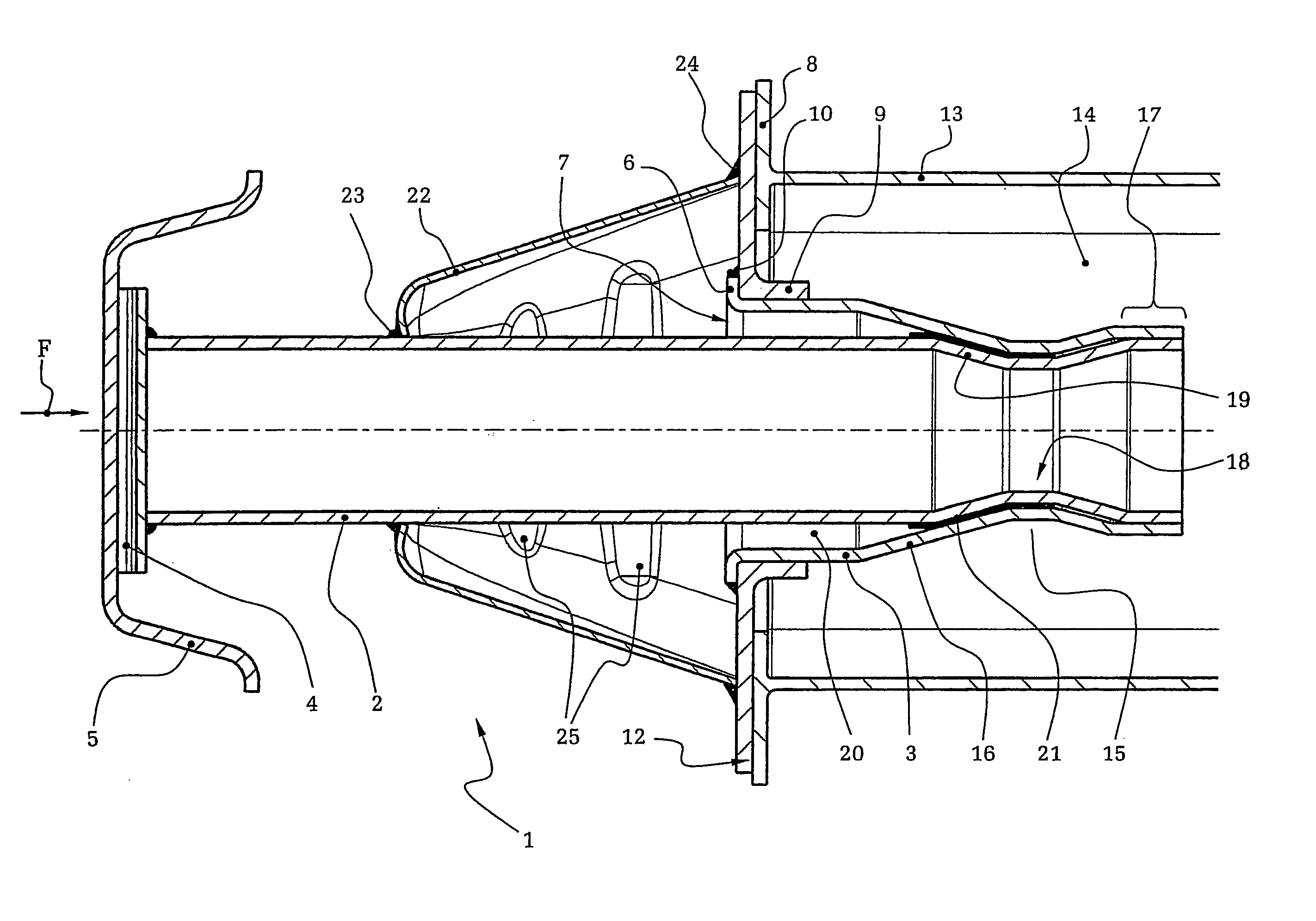
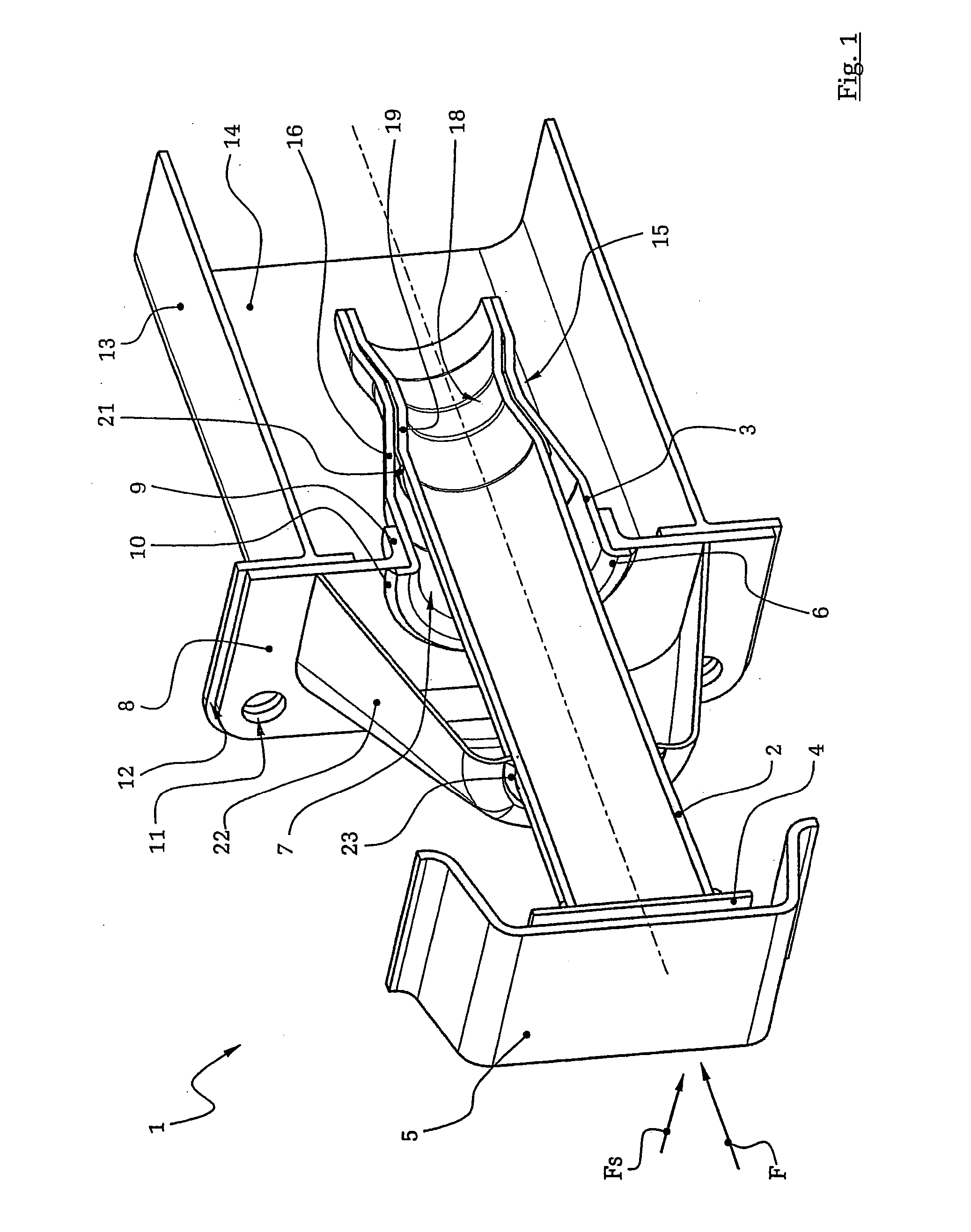
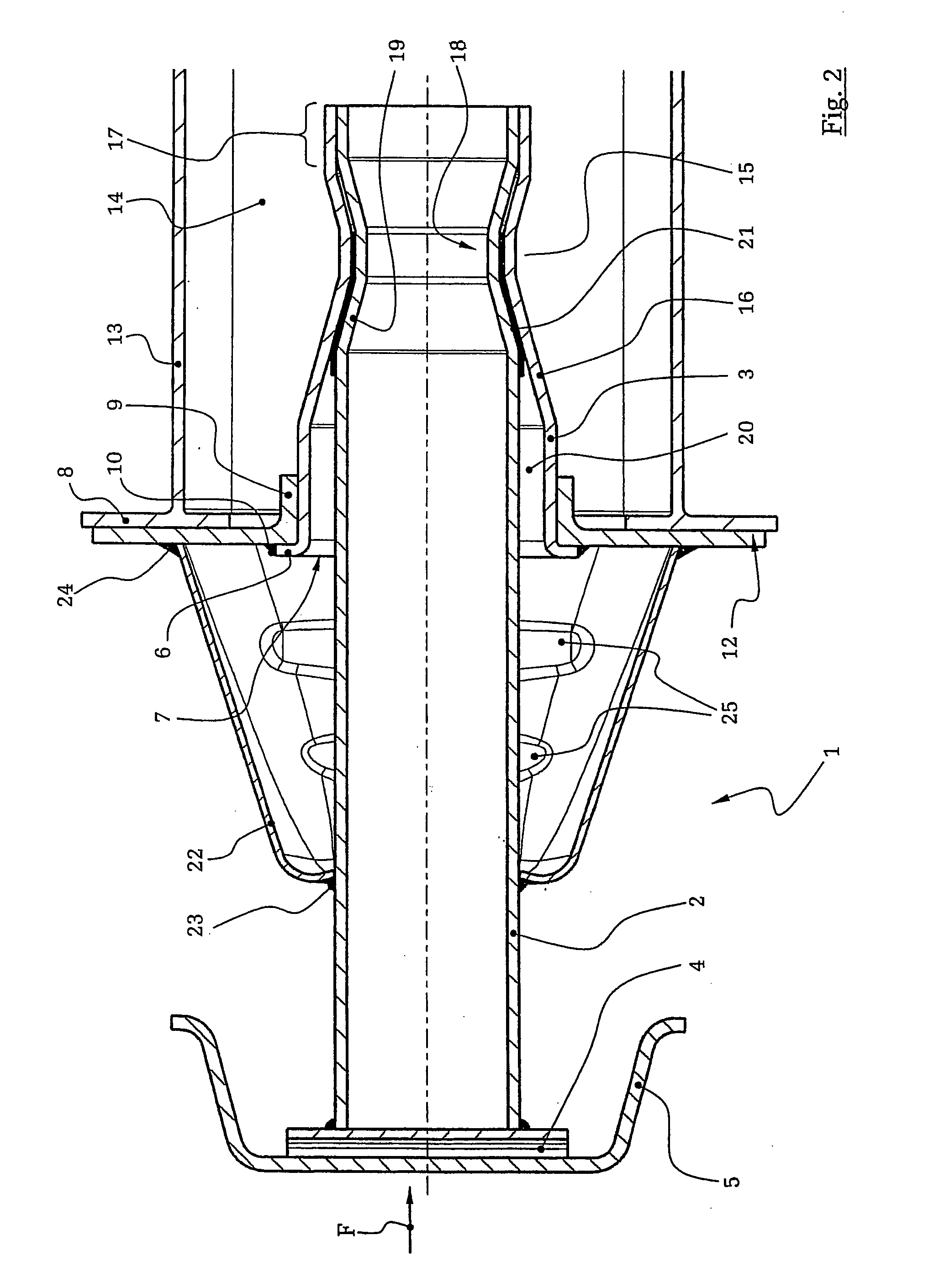
[0025]FIGS. 1 and 2 show an impact damper assembly 1 with an inner tube 2 disposed inside an outer tube 3. The inner tube 2 is connected by a mounting plate 4 with a bumper 5. The mounting plate 4 and the inner tube 2 are connected, for example, by a weld connection. The cross-section of the inner tube 2 and the outer tube 3 along their respective longitudinal axis is essentially circular, but can deviate from a circular shape depending on the requirements for stiffness.

[0026] The outer tube 3 has an outwardly protruding collar 6 which is supported against the edge of the recess 7 of a mounting flange 8. The recess 7 of the mounting flange 8 is formed with a tubular extension 9, whereby the outside wall of the outer tube 3 abuts the inside wall of the recess 7 or the tubular extension 9. In this exemplary embodiment, the outer tube 3 is connected along the collar 6 with the mounting flange 8 by a weld connection 10. Alternatively, the outer tube 3 and the mounting flange 8 can also...


PUM


Abstract

Impact damper assembly for an automobile, in particular for supporting a bumper 5 on an automobile chassis, with an inner tube 2 movably arranged in an outer tube 3, wherein both tubes 2, 3 have an approximately mutually parallel taper 16, 19, wherein the taper 19 of the inner tube 2 is encompassed by the taper 16 of the outer tube 3, and wherein at least one of the two tubes 2, 3 can be deformed during the movement by the taper 16, 19 of the two tubes. The invention is characterized in that the impact damper assembly includes an additional deformable stiffening element 22.

Description

BACKGROUND OF THE INVENTION [0001] 1. Field of the Invention [0002] The invention relates to an impact damper assembly for an automobile, with an inner tube movably arranged inside an outer tube, wherein at least one tube is deformable by a relative displacement between the two tubes caused by an impact. [0003] Such impact damper assemblies are employed in automobiles to convert the impact energy generated during a collision at least partially into deformation work. This arrangement minimizes damage to the automobile chassis, for example to the longitudinal chassis rails, and may even entirely prevent such damage at low speed. Damage to and deformation of the vehicle caused by a collision are reduced, which not only increases the safety for the vehicle occupants by maintaining the integrity of the passenger compartment, but also keeps the repair costs down. An insurer may also place the vehicle type in a more favorable insurance rating step. [0004] 2. Description of the Related Art ...

Claims


Application Information

Patent Timeline
IPC IPC(8): B60R19/26
CPCB60R2021/0009B60R19/34
Inventor HANSEN, THOMAS
Owner ZF FRIEDRICHSHAFEN AG
Why Eureka
Try Eureka