Stator and brushless motor

a stator and coil technology, applied in the direction of windings, rotating magnets, synchronous machines with stationary armatures, etc., can solve the problems of difficult to improve a space factor or the coil winding, the coil is difficult to be connected in parallel, and the work of the coil winding is complicated

Inactive Publication Date: 2006-02-02
ICHINOMIYA ELECTRIC
View PDF6 Cites 86 Cited by
  • Summary
  • Abstract
  • Description
  • Claims
  • Application Information

AI Technical Summary

Benefits of technology

[0028] The effects of the invention mentioned above is significant in the case that the number of the coils constituting the coil group of the same phase is an even number equal to or more than four, and the same effect can be obtained by a brushless motor wherein a stator is constituted by the above-mentioned stator.

Problems solved by technology

However, since a leading end side becomes narrow between the adjacent teeth portions, a coil winding work tends to be complicated, and it is not easy to improve a space factor or the coil winding.
However, as exemplified by the brushless motor 901 having 14 poles and 12 slots, if coils of the same phase have the arrangement in which the phase and the magnitude of the induction voltage are different, the coils capable of being connected in parallel are limited.
In such a stator, it is impossible to continuously wind all the divided core or the like of the same phase, and it is impossible to make the winding directions of the continuously wound coils identical.
However, the layout of the divided cores or the like at a time of assembling is deteriorated and the assembling work is hard to be executed in the case that the length of the crossover is shortened; therefore, it is impossible to make the crossover too short.
Further, the thick coil wire is used in the motor having a high torque; therefore, the crossover becomes thick, and a great force is required for forming the crossover bent in the U shape at the adjacent positions such as the coils 98a and 98b so as to appropriately receive the crossover for space saving, so that it is hard to work by a human power.

Method used


Image

  • Stator and brushless motor
  • Stator and brushless motor
  • Stator and brushless motor

Examples


Embodiment Construction

[0045] Description will be given below of an embodiment according to the invention with reference to the accompanying drawings in detail.

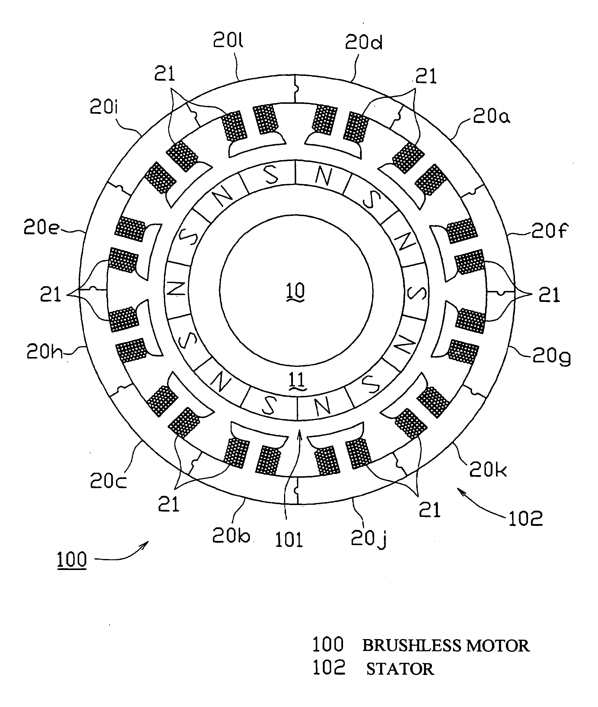
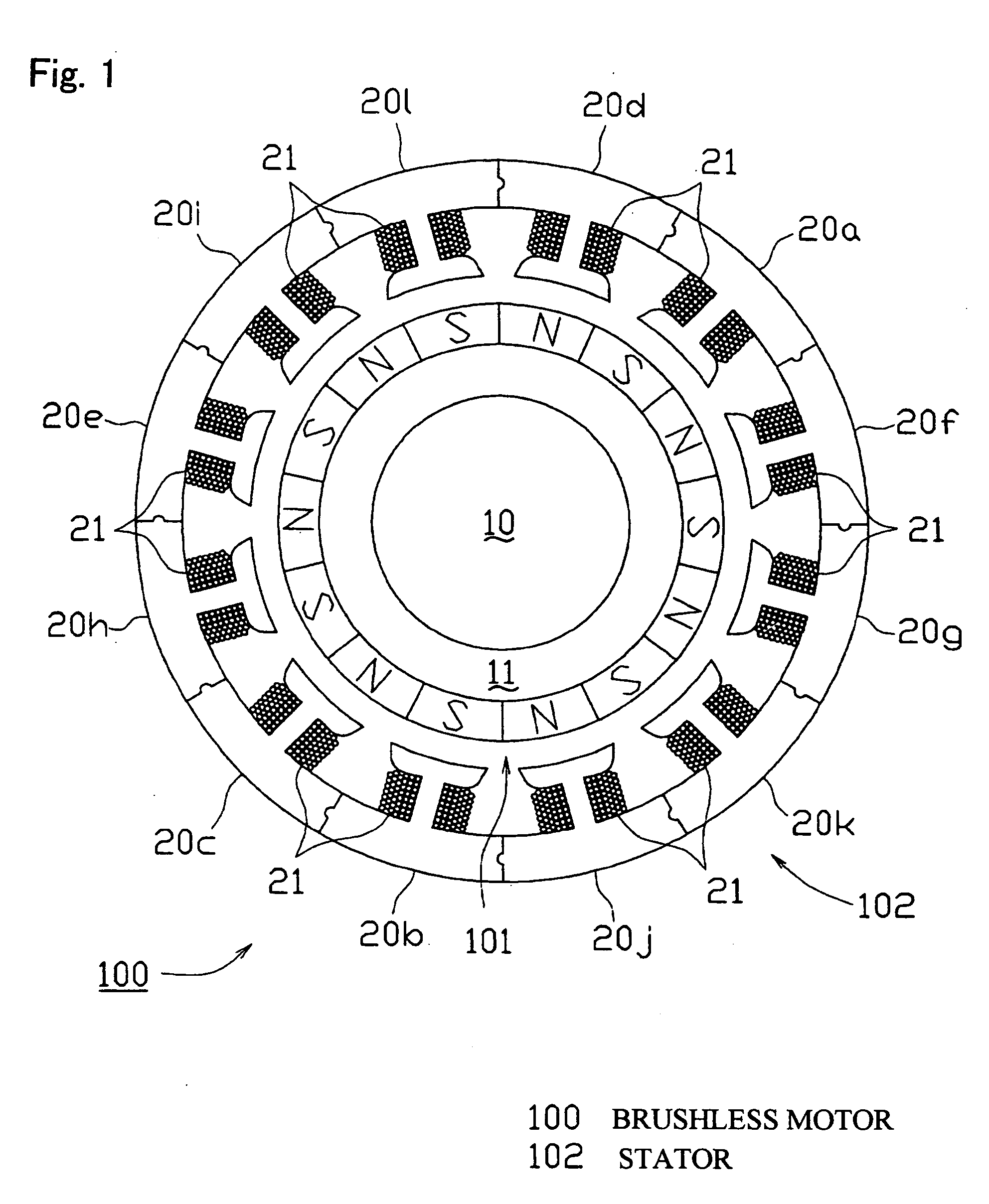
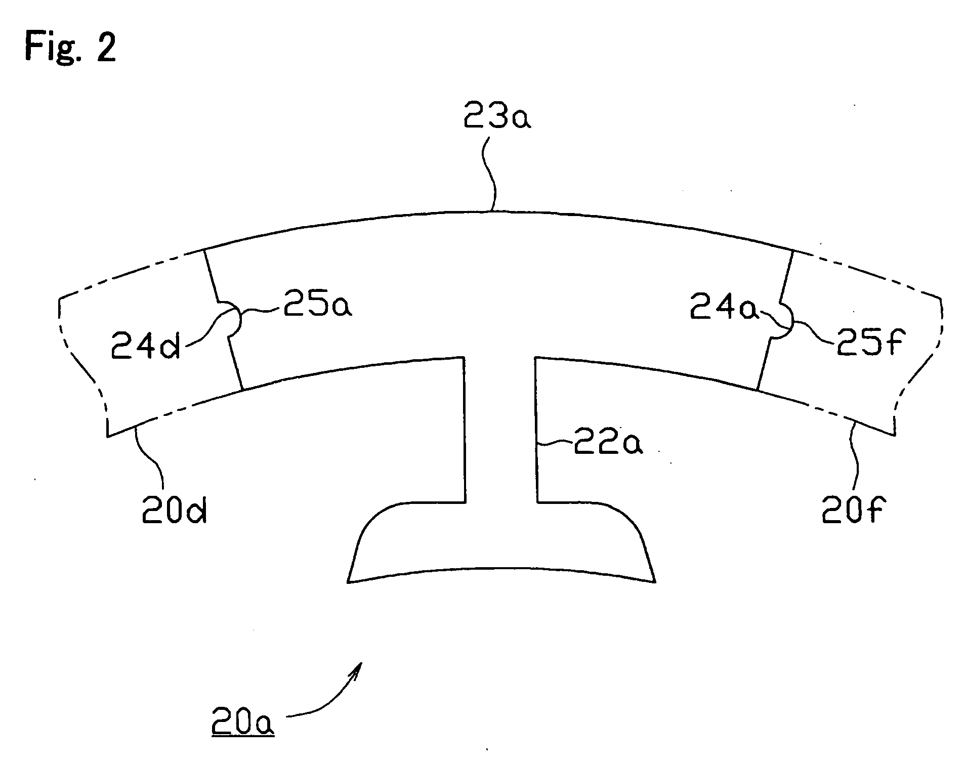
[0046] A brushless motor 100 according to an embodiment of the invention is of an inner rotor type constituted by an inner rotor and an outer stator. As shown in FIG. 1, the inner rotor is constituted by a rotor 101, and the outer stator is constituted by a stator 102 in which 12 divided cores 20a to 201 (not shown) divided every teeth are coupled in an annular shape, and coils 21 are wound around the respective teeth. The rotor 101 is rotatably disposed within the stator 102 with a fixed gap. In this case, the stator and the brushless motor according to the invention are not particularly limited in the number of motor poles and the number of slots, and can be carried out in a stator in which a plurality of coils constituting a coil group of the same phase are respectively arranged so as to include positions at which phases of induction voltage ar...


PUM


Abstract

The invention provides a technique of facilitating a coil winding work by continuously winding coils in the same direction, in a stator in which a plurality of coils constituting a coil group of the same phase are respectively arranged so as to include positions at which phases of induction voltage are different, whereby coil groups of three phases are disposed in a ring shape. A stator (102) of the invention has a structure in that a pair of coils (21U1, 21U4) and coils (21U2, 21U3) in which phases of induction voltage are identical in a plurality of coils (21U1 to 21U4) constituting a U-phase coil group (21U) are set as different divided groups, the respective coils (21U1, 21U4) and coils (21U2, 21U3) in the divided group are continuously wound in the same winding direction while arranging crossovers (26U1, 26U3) respectively between the coils (21U1, 21U4) and between the coils (21U2, 21U3), the divided groups are connected in parallel, and a V phase and a W phase are executed in the same manner, whereby lead wires of three-phase coil groups (21U, 21V, 21W) are star connected.

Description

BACKGROUND OF THE INVENTION [0001] 1. Field of the Invention [0002] The invention relates to a three-phase coil stator in which a plurality of coils are arranged in a ring shape. More particularly, the invention relates to a stator suitable for a stator of a brushless motor. [0003] 2. Description of the Related Art [0004] Various motors such as an induction motor and a commutator motor have been conventionally used as the motor. However, in recent years, a brushless motor which is made high performance has been frequently used. For example, an inner rotor type brushless motor has a structure in that a stator around which a plurality of coils are wound is formed as an outer stator and a rotor having a magnet arranged in an outer periphery is formed as an inner rotor. The stator is produced by applying a coil winding to a stator core in which a teeth portion for winding the coil is protruded to an inner side in a ring shape. However, since a leading end side becomes narrow between the...

Claims


Application Information

Patent Timeline
Patent Type & Authority Applications(United States)
IPC IPC(8): H02K1/00H02K3/00
CPCH02K1/148H02K21/16H02K3/28
Inventor KINASHI, YOSHIKAZU
Owner ICHINOMIYA ELECTRIC
Why Eureka
Try Eureka