Scheduling in an RFID system having a coordinated RFID tag reader array

Active Publication Date: 2006-02-02
QUAKE GLOBAL +1
View PDF34 Cites 516 Cited by
  • Summary
  • Abstract
  • Description
  • Claims
  • Application Information

AI Technical Summary

Benefits of technology

[0019] In accordance with the present invention, a system and method is provided for identifying and tracking tagged merchandise, personnel, and other items and/or individuals within an RFID environment with increased reliability. The presently disclos

Problems solved by technology

Because passive tags do not have a durable power source, they do not include active semiconductor circuitry and must therefore maintain data and state information statically within its embedded memory.
In addition, passive tags have an essentially unlimited life span, while the life span of active tags is typically limited by the lifetime of the internal battery, which in some implementations may be replaceable.
However, the conventional RFID systems described above have a number of drawbacks.
For an RFID system that includes a single RFID reader, the penetration ability of the reader is typically limited by the reader's maximum transmit power.
It may therefore be virtually impossible to infer the actual interrogation zone of the reader directly from the reader's transmission and reception settings and the transmission/reception capabilities of the tags.
Moreover, the interrogation zone of an RFID reader often fails to match the space that needs to be monitored in the RFID application.
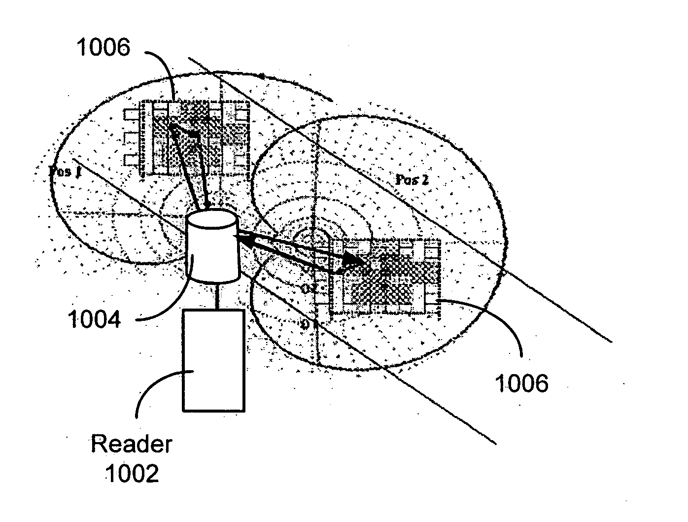
In addition, the conventional RFID system employing a single RFID reader is generally incapable of determining the location and/or direction of a moving RFID tag with precision.
For example, in the event an RFID tag is attached to a forklift truck at a warehouse storage facility, a single RFID reader may be unable to determine whether the forklift is leaving or entering the facility at it passes the reader, which may be disposed at a dock bay.
Conventional RFID systems that employ multiple RFID readers also have drawbacks.
However, such dense deployments of RFID readers are problematic due to RF interference and potentially con

Method used


Image

  • Scheduling in an RFID system having a coordinated RFID tag reader array
  • Scheduling in an RFID system having a coordinated RFID tag reader array
  • Scheduling in an RFID system having a coordinated RFID tag reader array

Examples


Embodiment Construction

[0055] The disclosure of U.S. Provisional Patent Application No. 60 / 592,933 filed Jul. 30, 2004 entitled ACCESSING RFID TAG DATA USING A READER ARRAY is incorporated herein by reference.

[0056] A system and method of accessing radio frequency identification (RFID) tag data is disclosed that provides enhanced coordination of multiple RFID readers with respect to frequency, time, space, and transmit power. The presently disclosed system employs at least one mid-level processing component and at least one host computer running client software applications. The mid-level processing component effectively transforms the operation of the RFID readers from an aggregated but essentially autonomous operating mode to a highly coordinated operating mode, in which the respective readers effectively function as elements of an RFID reader array. A system and method is also disclosed for scheduling tag interrogations by the plurality of readers so as to mitigate the effects of interference within a...


PUM


Abstract

A system and method of scheduling RFID tag interrogations by a plurality of RFID readers so as to mitigate the effects of interference within an RFID environment in which the readers are deployed, and to enhance the efficiency and reliability of the overall RFID system. The system includes a plurality of RFID receivers for receiving RFID tag data, a plurality of RFID tag interrogators for transmitting RF interrogation signals for interrogating RFID tags, and a controller for providing to at least one interrogator, at least one receiver, and at least one tag, a parameter associated with operational characteristics of the interrogator, the receiver, and the tag, respectively. The interrogator, the receiver, and the tag are operative, in response to receipt of the respective parameter, to modify its operational characteristics in accordance with the respective parameter, thereby avoiding interference at the receivers and the tags.

Description

CROSS REFERENCE TO RELATED APPLICATIONS [0001] This application claims benefit of U.S. Provisional Patent Application No. 60 / 592,933 filed Jul. 30, 2004 entitled ACCESSING RFID TAG DATA USING A READER ARRAY.STATEMENT REGARDING FEDERALLY SPONSORED RESEARCH OR DEVELOPMENT [0002] N / A BACKGROUND OF THE INVENTION [0003] The present invention relates generally to radio frequency identification (RFID) systems, and more specifically to a system and method of scheduling tag interrogations in an RFID system including a coordinated RFID tag reader array. [0004] In recent years, radio frequency identification (RFID) systems have been employed in an ever increasing range of applications. For example, RFID systems have been used in supply chain management applications to identify and track merchandise throughout manufacture, warehouse storage, transportation, distribution, and retail sale. RFID systems have also been used in security applications to identify and track personnel for controlling ac...

Claims


Application Information

Patent Timeline
IPC IPC(8): H04Q5/22
CPCG01S5/0252G01S5/06G06K7/0008G06K2017/0051G06K17/0029G06K2017/0045G06K2017/0048G06K7/10356G01S5/02525
Inventor KRISHNA, PATTABHIRAMANFISCHER, JEFFREY H.HUSAK, DAVID J.STEPHENSON, ROBERT A.
Owner QUAKE GLOBAL
Why Eureka
Try Eureka