Surface light source device and liquid crystal display device

a liquid crystal display and surface light source technology, applied in the direction of instruments, computing, electric digital data processing, etc., can solve the problems of prone to non-uniform and increasing the cost of manufacturing a backlight, so as to reduce the blurring of moving pictures on the screen display, increase the manufacturing cost, and uniform luminance of exit light

Active Publication Date: 2006-02-02
TRIVALE TECH
View PDF6 Cites 72 Cited by
  • Summary
  • Abstract
  • Description
  • Claims
  • Application Information

AI Technical Summary

Benefits of technology

[0029] In the surface light source device and the liquid crystal display device according to the invention, the light quantity detecting means which performs light quantity detection on the basis of output light beams that are led out from the two or more light emission blocks adjusts the emission light quantities by properly detecting emission light quantities of the light sources corresponding to the respective light emission blocks. This makes it possible to make light beams that are output from the respective light emission blocks of the light exit area uniform among the light emission blocks without the need for providing, for the respective light emission blocks, sensors for detecting, for the respective light emission blocks, emission light quantities of the light sources. This in turn makes it possible to suppress moving picture blurring in screen display a

Problems solved by technology

Liquid crystal display devices which perform screen display by illuminating a liquid crystal panel with a backlight from the back side has a problem a phenomenon that when a moving picture is displayed images are recognized visually so as to have tails (what is called “moving picture blurring”).
This results in a problem that the luminance of exit light is prone to be

Method used


Image

  • Surface light source device and liquid crystal display device
  • Surface light source device and liquid crystal display device
  • Surface light source device and liquid crystal display device

Examples


embodiment 1

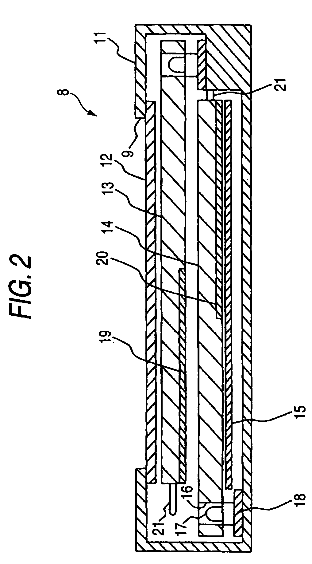
[0068]FIG. 1 is a schematic perspective view showing the configuration of an exemplary liquid crystal display device according to a first embodiment of the present invention, that is, a liquid crystal display device 1 that is composed of a liquid crystal panel 2 for a data writing operation on pixels and a backlight 8 for illuminating the liquid crystal panel 2 from the back side in synchronism with the data writing operation. The liquid crystal display device 1 according to this embodiment is a thin liquid crystal display that is superior in moving picture display characteristics and has a narrow frame area.

[0069] The liquid crystal panel 2 is a transmission-type display device having a counter substrate and a TFT (thin-film transistor) array substrate that hold a liquid crystal inbetween. A large number of pixels are arranged in matrix form in a display area 3 that is formed in the panel surface. In this example, the display area 3 has an oblong, rectangular shape and gate lines ...

embodiment 2

[0127]FIG. 17 is a sectional view showing the structure of an important part of an exemplary surface light source device according to a second embodiment of the invention. The surface light source device according to this embodiment is different from the backlight 8 of FIG. 2 (first embodiment) in that each of the confronting surfaces of light guide plates 52 and 54 is inclined toward the side (of the other end) that is opposite to the side where point light sources 57 are disposed.

[0128] As for the front light guide plate 52, the back surface is inclined toward the side of the other end. That is, the other end surface of the light guide plate 52 is thinner than the one end surface where the point light sources 57 are disposed. As for the rear light guide plate 54, the front surface is inclined toward the side of the other end. That is, the other end surface of the light guide plate 54 is thinner than the one end surface where the point light sources 57 are disposed. The light guid...

embodiment 3

[0136] The first and second embodiments are directed to the case that the diffusion pattern is formed on each of the light guide plates arranged in the front-rear direction on the side of the other end that is opposite to the side where the point light sources are disposed, whereby light that is input from each point light source to the associated light guide plate is output from it after being diffused sufficiently. In contrast, in this embodiment, light guide plates for diffusion are disposed behind a light guide plate for emission.

[0137]FIG. 19 is a sectional view showing the structure of an important part of an exemplary surface light source device according to a third embodiment of the invention. The surface light source device according to this embodiment is composed of a light guide plate 71 for light emission that is disposed on the front side, two light guide plates 74 for light diffusion that are disposed on the rear side, side reflectors 75 that are disposed on both side...


PUM


Abstract

A surface light source device includes light source driving means for driving light sources on a light emission block basis, a light exit area being sectioned into two or more light emission blocks, light quantity detecting means for detecting light quantities on the basis of output light beams that are led out from the two or more light emission blocks, and drive control means for adjusting emission light quantities of the light sources corresponding to the respective light emission blocks on the basis of light quantities that are detected during lighting periods when only one of the light emission blocks is lit up that are subjected to light quantity detection by the light quantity detecting means.

Description

BACKGROUND OF THE INVENTION [0001] 1. Field of the Invention [0002] The present invention relates to a surface light source device and a liquid crystal display device and, more specifically, to improvement of a surface light source device as a backlight for illuminating, from the back side, a liquid crystal panel which writes data to pixels. [0003] 2. Description of the Related Art [0004] Liquid crystal display devices which perform screen display by illuminating a liquid crystal panel with a backlight from the back side has a problem a phenomenon that when a moving picture is displayed images are recognized visually so as to have tails (what is called “moving picture blurring”). To suppress such moving picture blurring, a conventional technique of turning on the backlight in synchronism with data writing to the pixels of the liquid crystal panel was proposed (e.g., JP-A-2001-210122 and JP-A-2003-57622). [0005] In a backlight disclosed in JP-A-2001-210122, a single light guide plate...

Claims


Application Information

Patent Timeline
IPC IPC(8): G09G3/36
CPCG02B6/0028G02B6/0031G02B6/0055G09G2360/145G02B6/0078G09G3/3413G09G3/3611G02B6/0076
Inventor SAKAI, SEIJISAKAMOTO, TAKUYAYONEDA, TOSHIYUKI
Owner TRIVALE TECH
Why Eureka
Try Eureka