
Object detection method for vehicles

a technology for objects and vehicles, applied in the field of objects detection methods for vehicles, can solve the problems of grids of this kind that cannot be flexibly adapted to the particular function or to the specific application, and the search area size is too large, so as to achieve simple and cost-effective detection performan

Inactive Publication Date: 2006-02-02
DAIMLER AG
View PDF7 Cites 24 Cited by
  • Summary
  • Abstract
  • Description
  • Claims
  • Application Information

AI Technical Summary

Benefits of technology

[0032] An object of the present invention is to provide a simple and cost-effective method of the type mentioned at the outset, which will provide a detection performance that is improved over conventional methods.
[0033] The present invention provides an object detection method for vehicles, which employs at least one sensor (S) for cyclically detecting a vehicle's surroundings whose measured values (M) are projected into a freely definable grid and are combinable into grid-based segments that can be assigned to identified objects (O), and, in accordance with which, tracks for these objects (O) are ascertained which can be used for controlling vehicle functions. According to the method, the cells (Z) of the grid (G) are designed to have incremental dimensions that differ in the radial and / or circumferential direction in such a way that a functionally optimized object resolution is achieved.
[0034] In contrast to segmentation based merely on distance criteria, the use of a grid for segmenting and first filtering of the measured values constitutes a very general and adaptable approach, which greatly simplifies the process of combining the individual measuring planes in particular.

Problems solved by technology

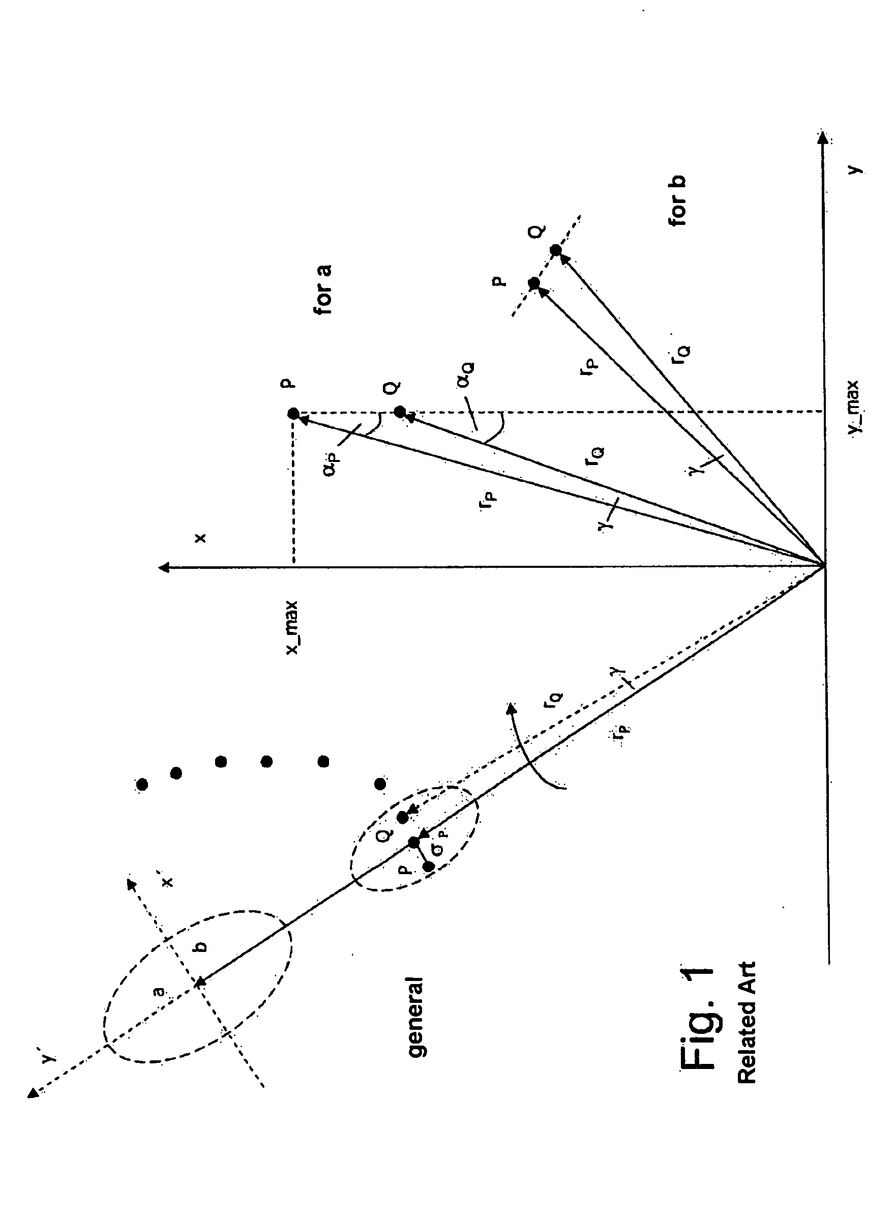
This means, however, that the disadvantages associated with search area size likewise arise when working with rectangular, circular or elliptical search areas, i.e., the search areas are dependent on distance r and incident radiation angle α. Thus, a grid of this kind is not able to be flexibly adapted to the particular function or to the specific application.

Method used


Image

  • Object detection method for vehicles
  • Object detection method for vehicles
  • Object detection method for vehicles

Examples


Embodiment Construction

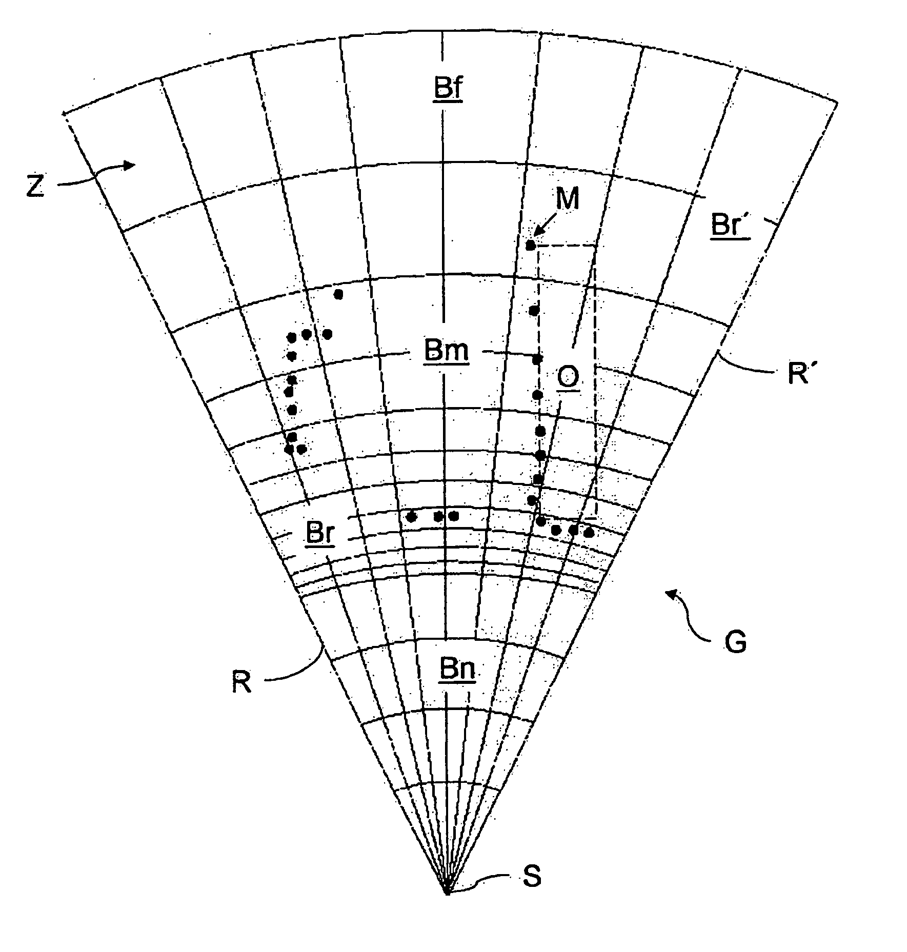
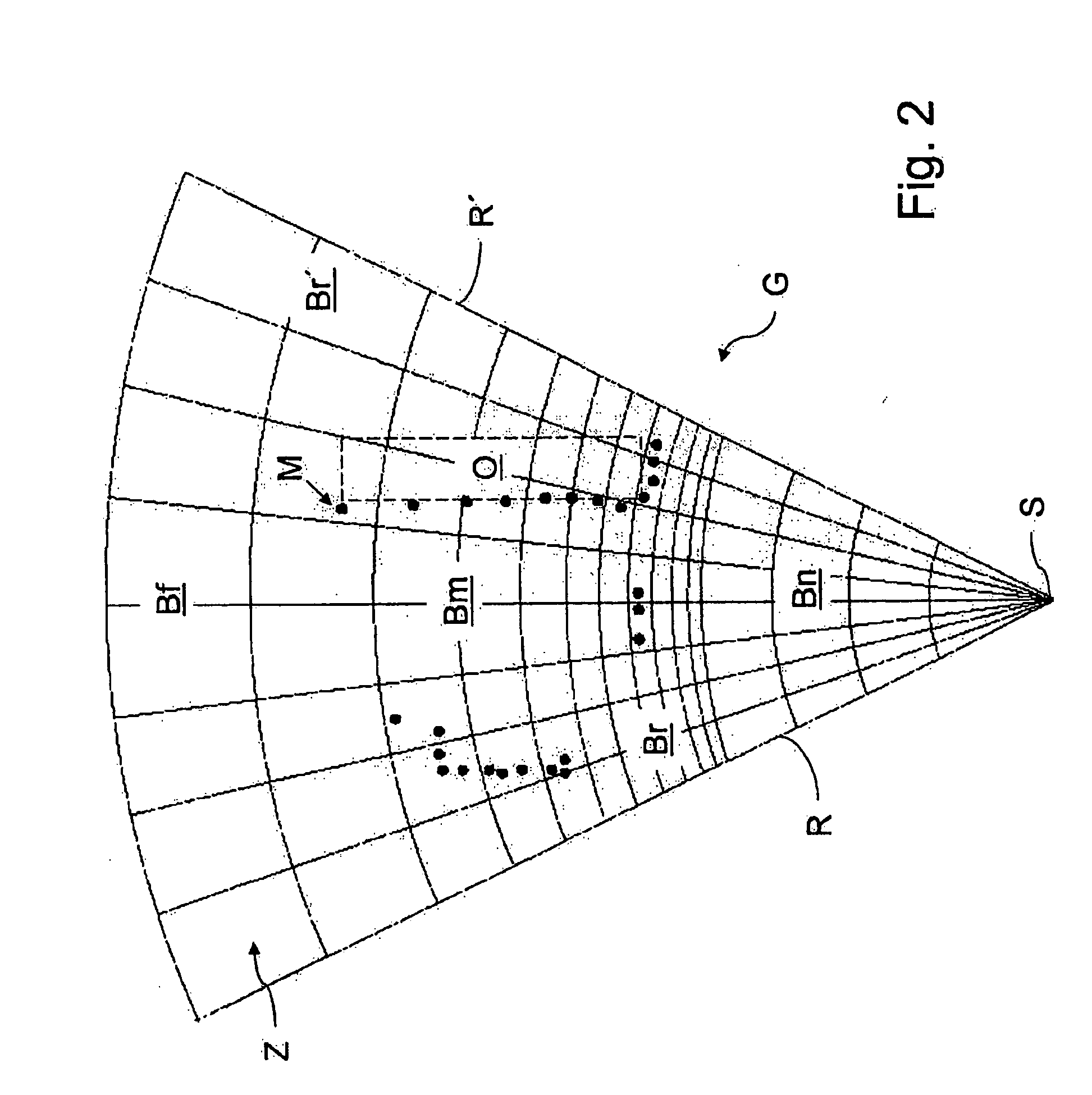
[0055]FIG. 2 shows exemplarily a grid G, whose near region Bn relative to a sensor S has an equidistant incremental dimension of cells Z. The incremental dimension of cells Z increases geometrically from a middle region Bm and into a far region Bf. Measured values of potential collision objects O (one of which is plotted exemplarily in grid G), recorded by sensor S, of all detection planes are projected into grid G, and, based on the number of measuring points per cell, it is ascertained which of cells Z is occupied. Cells that belong together are grouped by an appropriate cluster algorithm, and this result is projected onto the raw data in order to segment the same. Groups of raw data are formed which are assigned to an object and are used for determining tracks of the objects. In this context, each track represents a potential collision object, each actual destination being represented by at least one track. The tracks may be used, for example, for controlling safety systems, such...


PUM


Abstract

An object detection method for vehicles, which employs at least one sensor S for cyclically detecting a vehicle's surroundings whose measured values M are projected into a freely definable grid G and are combinable into grid-based segments that can be assigned to identified objects O, and, in accordance with which, tracks for these objects O are ascertained which can be used for controlling vehicle functions. The cells Z of the grid G are designed to have incremental dimensions that differ in their incremental dimensions in the radial and / or circumferential direction in such a way that a functionally optimized object resolution is achieved.

Description

[0001] Priority is claimed to German Patent Application No. DE 10 2004 032 118.3, filed on Jul. 1, 2004, the entire disclosure of which is incorporated by reference herein. [0002] The present invention relates to an object detection method for vehicles, which employs at least one sensor for cyclically detecting a vehicle's surroundings whose measured values are projected into a freely definable grid and are combinable into grid-based segments that can be assigned to identified objects, and, in accordance with which, tracks for these objects are ascertained which can be used for controlling vehicle functions. BACKGROUND [0003] Here, the concept of segmentation implies combining a plurality of measuring points from the raw data of a laser scanner, for example, on the basis of specific criteria. The aim of the segmentation process is to subdivide the raw data into segments which can be allocated to real objects in the sensor's visual detection range. Problems can arise due to potential...

Claims


Application Information

Patent Timeline
Patent Type & Authority Applications(United States)
IPC IPC(8): G06K9/00G01S17/931
CPCG01S7/4802G01S17/936G01S17/66G01S13/726G01S17/931
Inventor DICKMANN, JUERGENSKUTEK, MICHAELPRASANNA, RAJAN
Owner DAIMLER AG
Learn More