
Method for transmitting data signals and additional signals in an optical network

a data signal and optical network technology, applied in the direction of electromagnetic transmission, transmission, electrical apparatus, etc., can solve the problems of difficult to transmit this information via amplifiers and regenerators without damaging the signal quality, affecting the transmission effect, so as to achieve the effect of convenient extraction and optimal signal-to-noise ratio

Inactive Publication Date: 2006-02-02
SIEMENS AG
View PDF2 Cites 13 Cited by
  • Summary
  • Abstract
  • Description
  • Claims
  • Application Information

AI Technical Summary

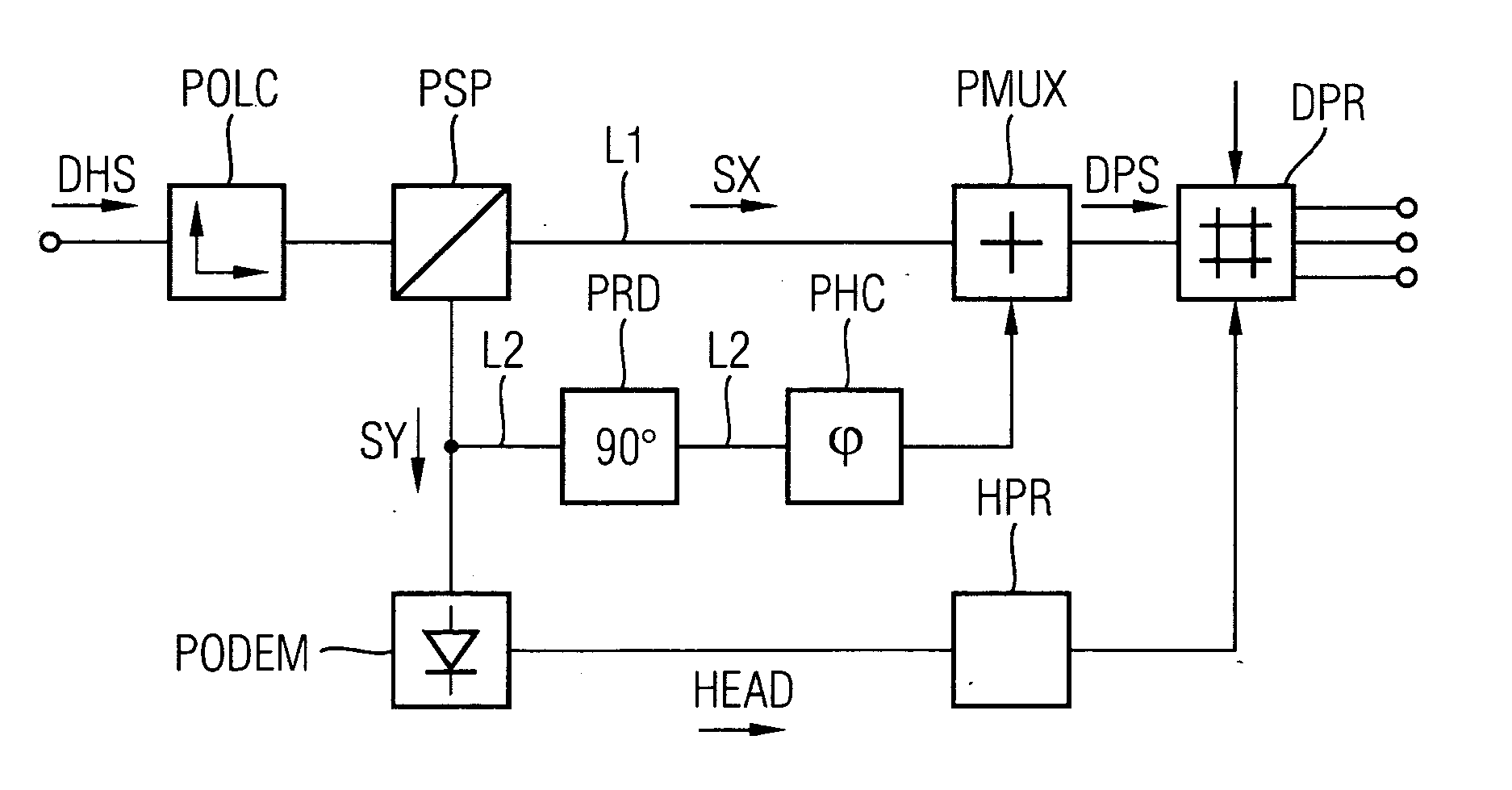
Benefits of technology

[0004] The prefixing of the header signifies a loss of transmission capacity. One possibility of avoiding this is an additional modulation of the data signal for the transmission of the header. It is difficult however to transmit this information via amplifiers and regenerators without damaging the signal quality. On the other hand, the transmission of the header together with the payload, known as ‘optical labeling’ ensures a considerable improvement in the transmission capacity.
[0005] The conventional transmission of the header via a separate (electrical) network, known today as burst switching, can also be avoided in a similar manner.
[0008] IEEE Photonics Technology Letters, Vol. 16, No. 7, July 2004, pages 1766-1768 describes a transmission method in which difference phase modulation and polarization modulation (pole shift keying) are combined. The demodulation device works with rectified components of the signals transmitted in the two polarization levels. The sensitivity is correspondingly lower and unequal delays of the polarized signals once again reduce the transmission performance during phase difference modulation.
[0011] A particular advantage of the known method is that only one carrier signal is ever transmitted, said carrier signal comprising different polarizations. In this way, an optimal signal-to-noise ratio is achieved.
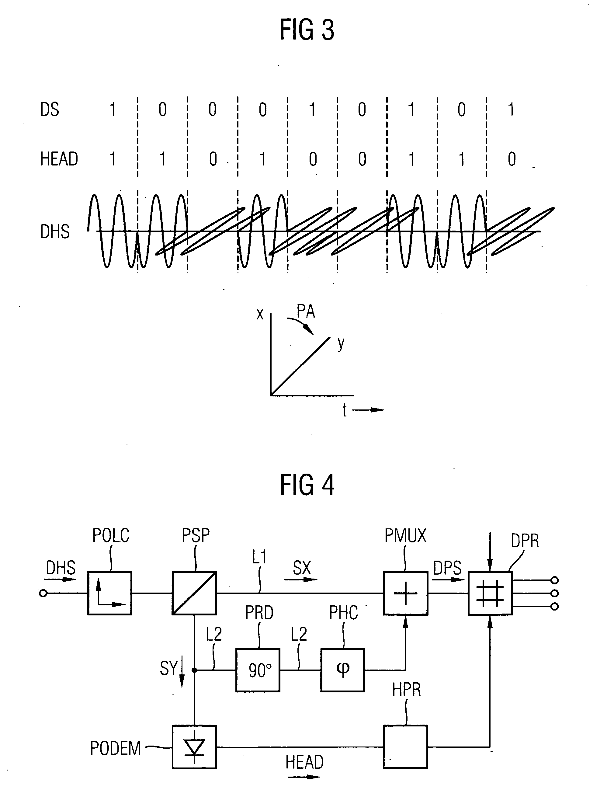
[0012] The combination of angular modulation and polarization modulation enables an easy extraction of the header / additional information in the optical domains, without the need for the data signal to be converted into the electrical domains. Similarly, a new header can be added to the optical data signal.

Problems solved by technology

It is difficult however to transmit this information via amplifiers and regenerators without damaging the signal quality.
One fundamental problem with the optical signal transmission is also that of extracting the header.
The conversion of the header and payload into electrical signals is associated with considerable costs and thus involves a reduction in the transmission capacity as a result of additional delays.

Method used


Image

  • Method for transmitting data signals and additional signals in an optical network
  • Method for transmitting data signals and additional signals in an optical network
  • Method for transmitting data signals and additional signals in an optical network

Examples


Embodiment Construction

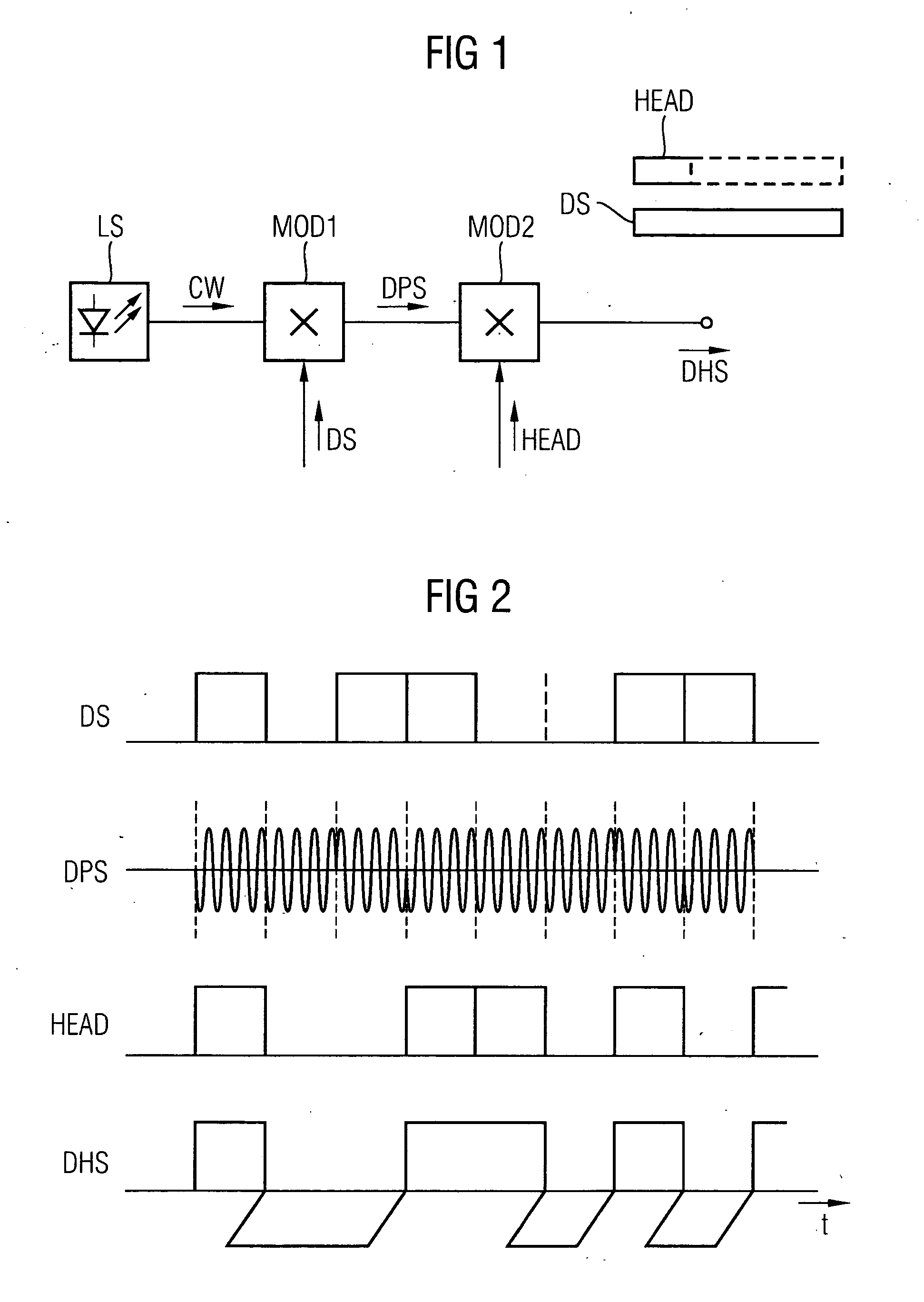
[0019]FIG. 1 shows a transmission device. A data signal is to be transmitted in the form of data bursts, to which is assigned a header in each instance. The data signal can thus be present in the form of so-called data packets or IP packets. This part of the transmission device is known and is not part of the invention which relates to the transmission method.

[0020] A laser LS generates a carrier signal plus CW which is angular modulated in a first modulator M0D1 by the data signal DS. It is thus advantageous here to use the fail-safe difference phase modulation. The angular modulated signal DPS is supplied to a second modulator M0D2, which polarizes it in accordance with the binary statuses of an additional signal HEAD. In this way, with a logical ‘1’ of the header for example, the polarization is not changed and with a logical ‘0’, the polarization is rotated about 90°. The multiplex signal DHS generated in this way is then combined if necessary with further multiplex signals to ...


PUM


Abstract

The transmission of a data signal (DS) in the form of data packets takes place by means of angular modulation, preferably two or three stage difference phase modulation. The header (HEAD) is transmitted by means of polarization modulation. An additional channel formed in this way is also available for the transmission of additional information. To separate the header (HEAD), the multiplex signal (DHS) is aligned in a specific polarization level, so that the header can be separated without any problem. A new header can be added without having to convert the data signal into an electrical signal beforehand.

Description

CROSS REFERENCE TO RELATED APPLICATIONS [0001] This application claims priority to the German application No. 10 2004 036 493.1, filed Jul. 28, 2004 and which is incorporated by reference herein in its entirety. FIELD OF INVENTION [0002] The method relates to the transmission of data signals and additional signals or an associated header in an optical network and a suitable arrangement therefor. SUMMARY OF THE INVENTION [0003] Optical networks have hitherto mostly been designed as point-to-point connections. Future networks will however be designed in a more flexible manner. In addition to the hitherto conventional transmission of optical data in permanently assigned channels, methods for the transmission of optical data packets will emerge which are known as burst switching and packet switching. With packet transmission each data packet needs to be provided with a so-called header, which prefixes the actual information, the data signal, of the so-called ‘payload’. The packet end ca...

Claims


Application Information

Patent Timeline
IPC IPC(8): H04B10/00H04B10/532
CPCH04B10/532
Inventor HECKER, NANCYJANSEN, SANDERVAN DEN BORNE, DIRK
Owner SIEMENS AG
Learn More