Device for assisted movement of a disabled leg

a technology for disabled legs and wheelchairs, applied in the direction of resilient force resistors, walking aids, physical therapy, etc., can solve the problems of muscle contraction when lifting the leg, leg control is still a problem, and the leg cannot be effectively controlled for simple activities

Inactive Publication Date: 2006-02-02
HOUSE JAMES H
View PDF17 Cites 7 Cited by
  • Summary
  • Abstract
  • Description
  • Claims
  • Application Information

AI Technical Summary

Benefits of technology

[0018] It is still another object of the present invention to provide a device for protected motion of an injured knee.

Problems solved by technology

An injury to the knee such as a rupture of the quadriceps (thigh) muscle that separates it from the patella (kneecap) leaves the leg without effective control for simple activity.
Crutches and a knee splint are typically provided after a knee injury, but leg control is still a problem.
Even when a knee splint is worn, the muscle will contract when lifting the leg and re-injury is a significant risk during simple activities such as getting into bed or into a car.
After knee surgery, the pain associated with movement often causes patients to keep the joint immobile.
This immobility may result in the tissue around the joint becoming stiff and scar tissue formation resulting in a joint that has a limited range of motion.
Once the joint stiffens and scar tissue forms, it can take months of physical therapy to recover that motion.
However, the CPM machines have several disadvantages.
Th

Method used


Image

  • Device for assisted movement of a disabled leg
  • Device for assisted movement of a disabled leg
  • Device for assisted movement of a disabled leg

Examples


Embodiment Construction

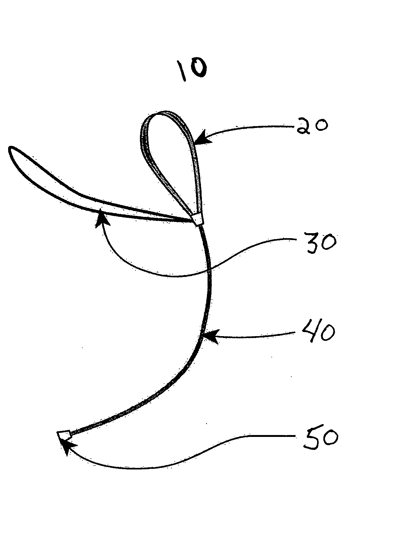
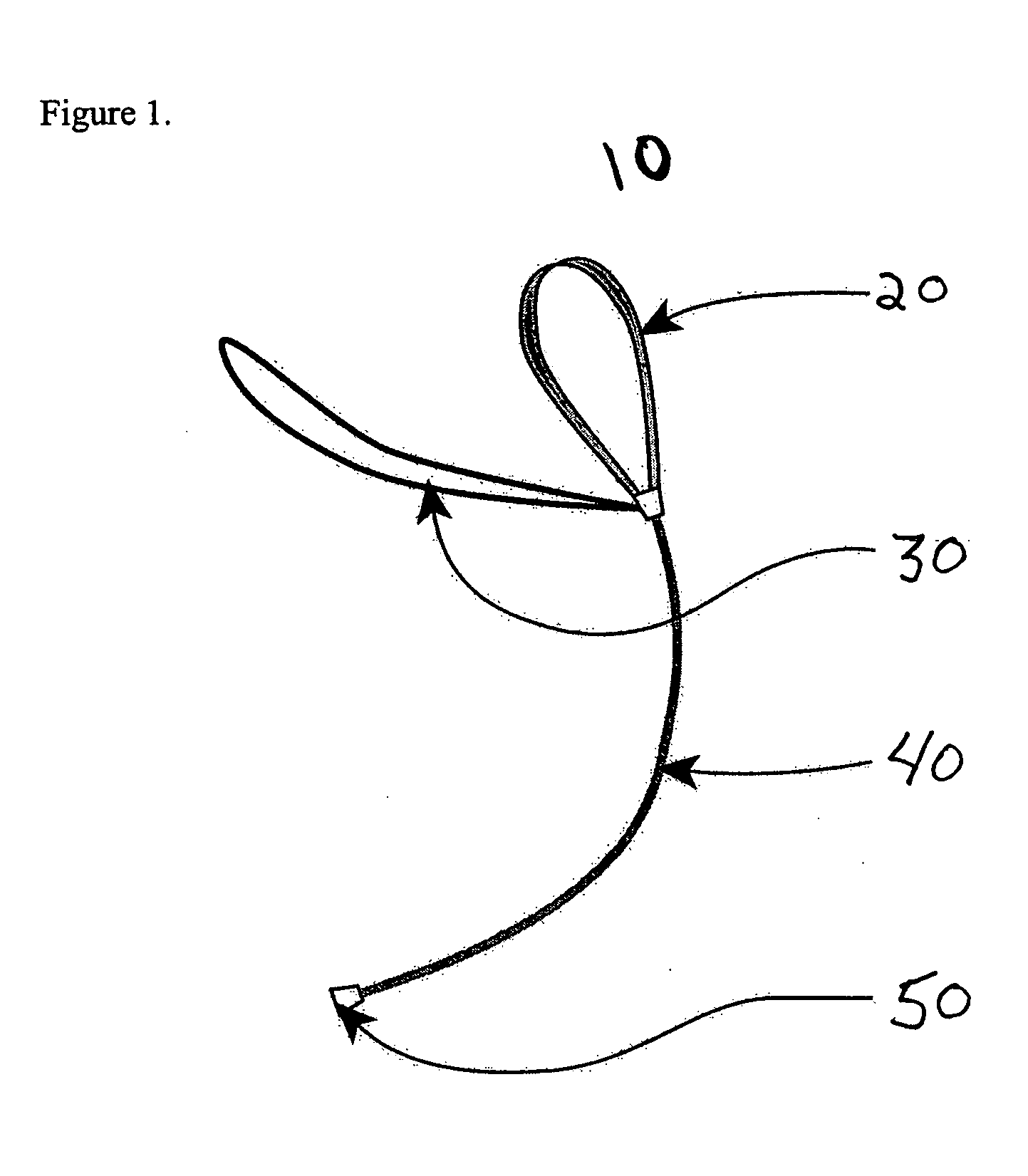
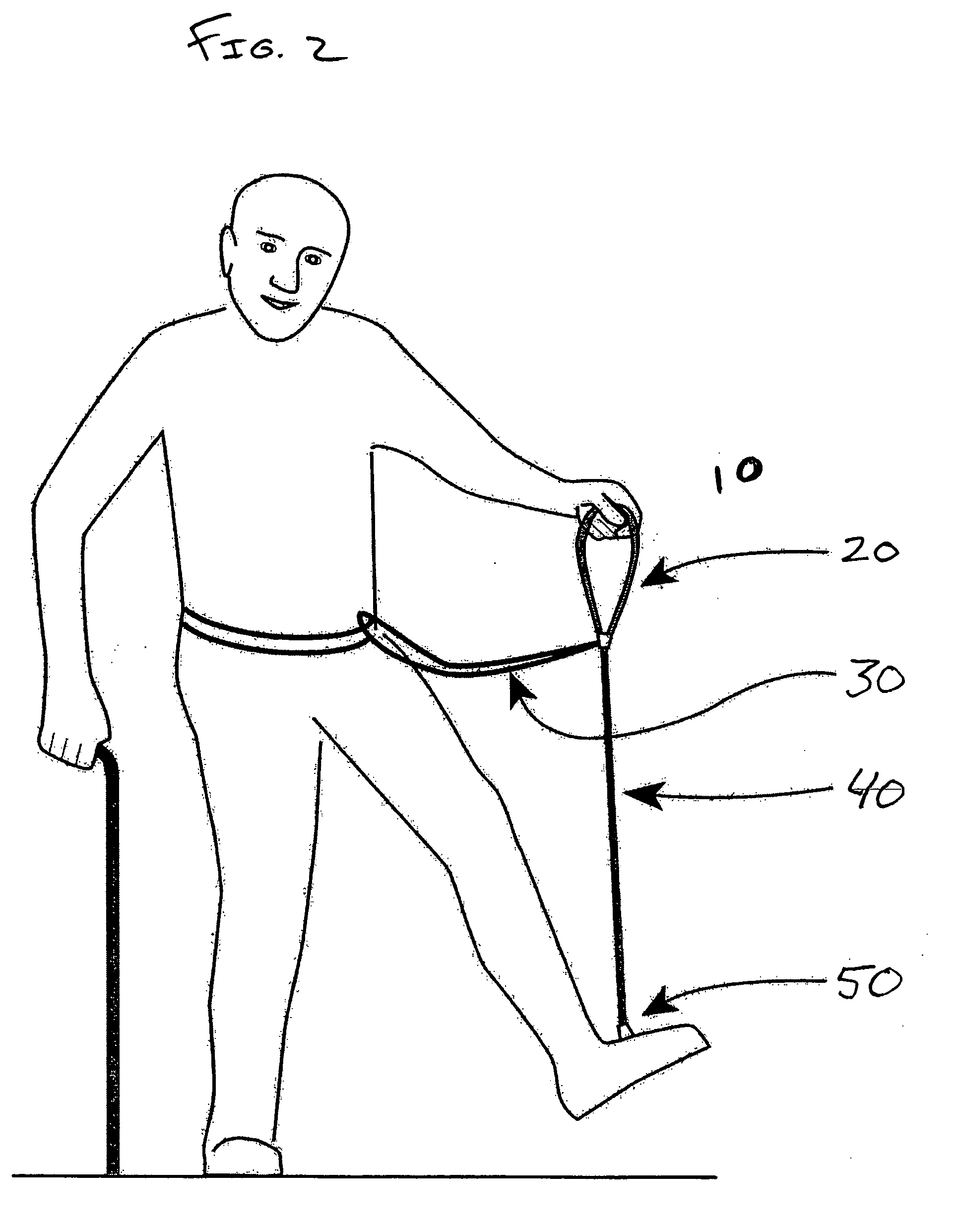
[0022] Referring to FIG. 1 the device 10 includes a handle 20 on its proximal end. The handle 20 may be configured to allow the user direct handheld manipulation of the device 10 to administer motive force to the user's leg at will without risk of re-injury or pain. The device 10 may be attached on or about the user's foot or footwear via the distal attachment apparatus 50. A dynamic elastic force mechanism 40 extends longitudinally between the handle 20 and the distal attachment apparatus 50.

[0023] Handle 20 may be a strap configured in a loop and constructed of fabric or other suitable material. In another embodiment, the handle 20 may be a loop formed integrally into the dynamic elastic force means. Alternatively, handle 20 may be a simple handgrip constructed of a semi-rigid molded plastic or any other suitable material. As shown in FIG. 2, the handle 20 is placed conveniently at or about the user's waist. This handle 20 placement provides the user with the ability to administe...


PUM


Abstract

The present invention is a device for controlled assisted movement of a disabled and/or injured leg. The device includes a dynamic elastic force member that extends longitudinally between a proximal end and a distal end of the dynamic elastic force member. The device further includes a handle operably coupled to the proximal end of the dynamic elastic force member and a suspension apparatus operably coupled to the proximal end of the dynamic elastic force member. Further, the device includes an attachment apparatus operably coupled to the distal end of the dynamic elastic force member. The device exerts a motive force that assists in movement of the leg when the user pulls the handle.

Description

FIELD OF THE INVENTION [0001] The present invention relates generally to the field of kinesitherapy for exercising a joint or limb, more particularly, the present invention provides for controlled assisted movement of a disabled leg after injury or surgery and to facilitate the recovery of a natural range of motion. BACKGROUND OF THE INVENTION [0002] An injury to the knee such as a rupture of the quadriceps (thigh) muscle that separates it from the patella (kneecap) leaves the leg without effective control for simple activity. Even after the application of a knee splint that holds the knee completely straight, there is a need for the injured person to be able to control their own limb while moving about, particularly when attempting to lift the injured leg against the force of gravity. Such control of a limb is required for simple activities like lifting the leg into a car or anytime limbs are mobilized postoperatively. [0003] Crutches and a knee splint are typically provided after ...

Claims


Application Information

Patent Timeline
IPC IPC(8): A63B21/02
CPCA61H3/00A61H2201/1269A61H2201/1635A61H2201/1642
Inventor HOUSE, JAMES H.
Owner HOUSE JAMES H
Why Eureka
Try Eureka