Travel time display device and method for industrial robot

a technology for industrial robots and display devices, applied in the field of industrial robots, can solve the problems of time-consuming processing for setting and changing transport routes, and achieve the effect of effective utilization

Active Publication Date: 2006-02-02
TOSHIBA MASCH CO LTD
View PDF4 Cites 4 Cited by
  • Summary
  • Abstract
  • Description
  • Claims
  • Application Information

AI Technical Summary

Benefits of technology

[0010] The present invention has been made in view of the above situation in the background art. It is therefore an object of the present invention to provide a travel time display device and method for an industrial robot which can display travel time on the screen in such a manner that time taken for moving a work from any designated starting point to any other point can be seen at a glance, so that the display can be effectively utilized as information for determining a starting point and an objective point from the standpoint of transport efficiency.

Problems solved by technology

On the other hand, an industrial robot needs to be instructed of a work traveling route, and setting and change of a transport route generally requires a time-consuming processing.

Method used


Image

  • Travel time display device and method for industrial robot
  • Travel time display device and method for industrial robot
  • Travel time display device and method for industrial robot

Examples


first embodiment

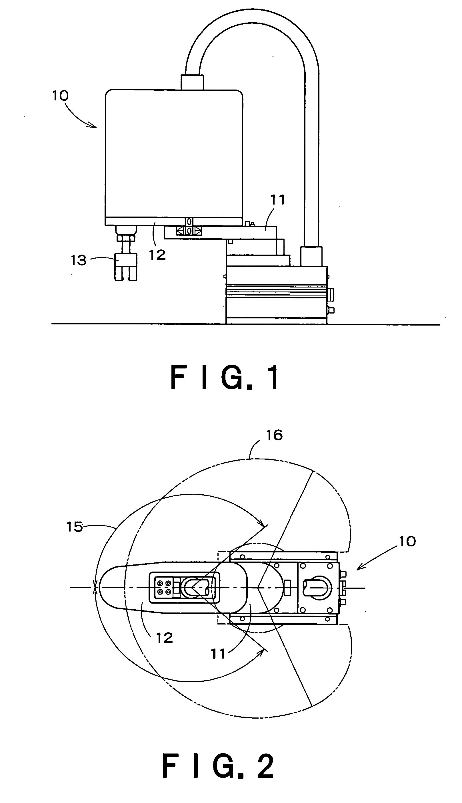
[0028]FIG. 1 is a side view of an industrial robot to which the present invention can be applied, and FIG. 2 is a plan view of the industrial robot of FIG. 1. In FIGS. 1 and 2, reference numeral 10 denotes the entirety of the industrial robot. The robot arm of the industrial robot is comprised of a first pivot arm 11 and a second pivot arm 12, and an end effector for clamping a work is mounted to the second pivot arm 12. The industrial robot 10 has a first shaft and a second shaft respectively for pivoting the first pivot arm 11 and the second pivot arm 12 in a horizontal plane, and a third shaft for vertically moving the end effector 13. In FIG. 2, the range surrounded by the curve 15 corresponds to the pivoting range of the second pivot arm 12. The overall traveling range, determined by the traveling ranges of the first and second pivot arms, corresponds to the range surrounded by the curve 16.

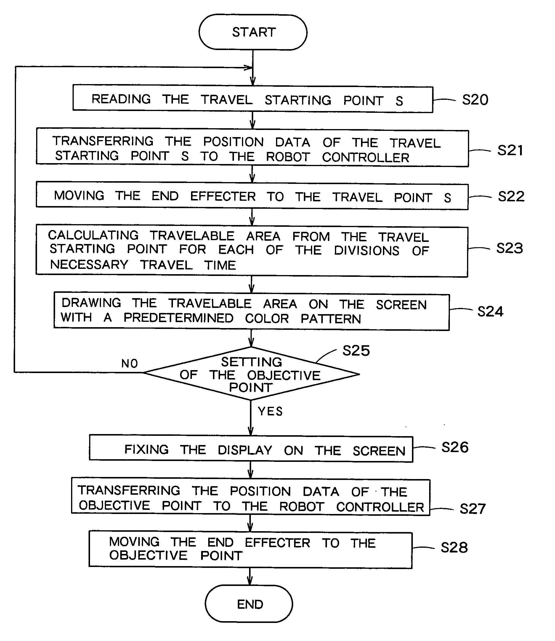
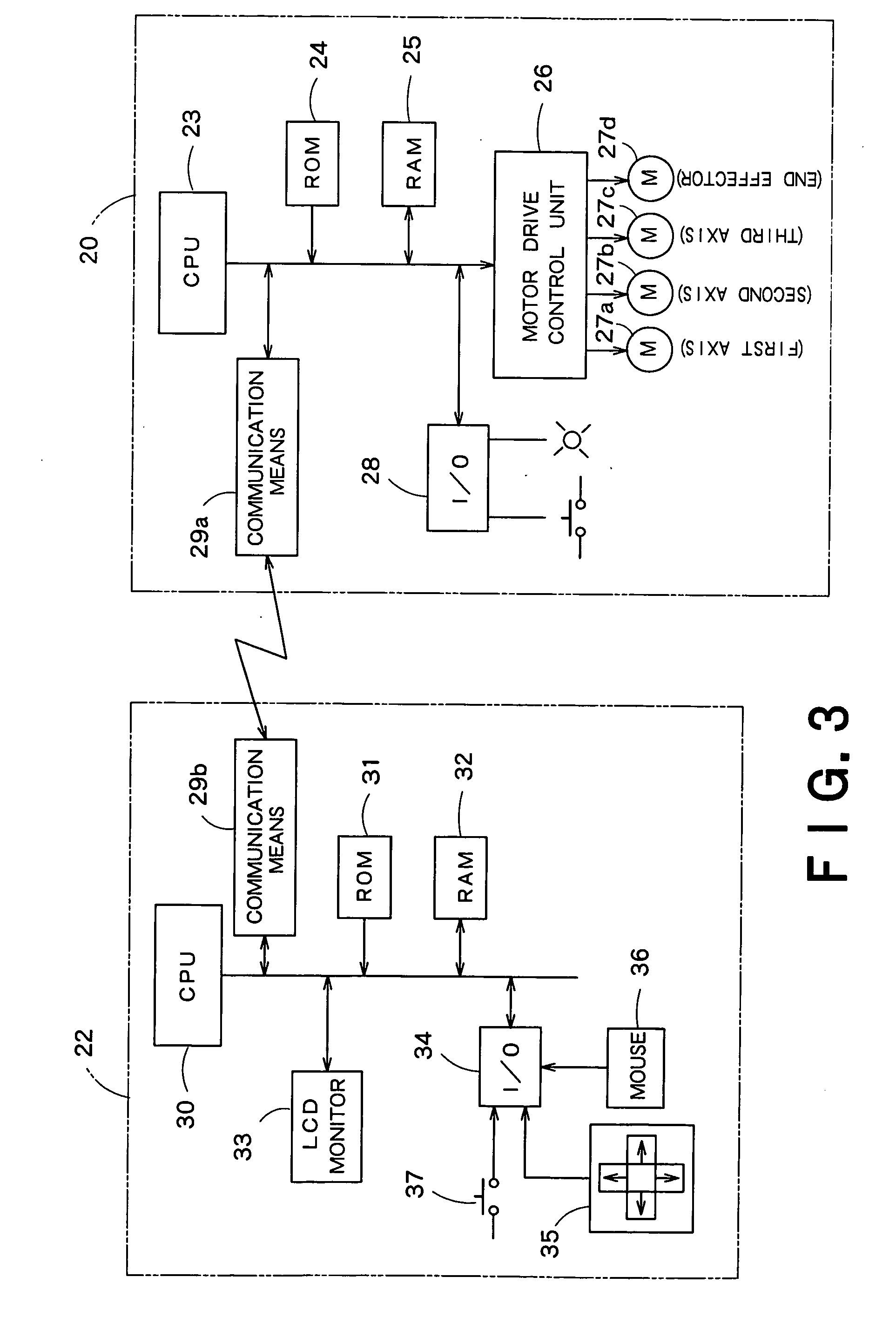
[0029]FIG. 3 is a block diagram showing a control system for the industrial robot of FI...

second embodiment

[0051] The second embodiment intends to determine the travelable area of the articulated industrial robot of FIG. 1 from the travel distances of the respective shafts and according to the operations of the shafts.

[0052]FIG. 9 is a diagram schematically showing the robot arm of the industrial robot shown in FIG. 1. The basic idea of travel time display according to the second embodiment is described at the outset with reference to FIG. 9.

[0053] Work Traveling Conditions:

[0054] (1) The end effector travels from a travel starting point to an objective point through the pivot movements of the first shaft and the second shaft, and does not always travel the shortest distance between the travel starting point and the objective point.

[0055] (2) The pivoting velocities of the first axis and the second axis are constant.

[0056] According to the second embodiment, a position in the operation area of the industrial robot can be specified in a polar coordinate system. In FIG. 9, the positio...


PUM


Abstract

There is provided a travel time display device for an industrial robot which can display travel time on the screen such that time taken for moving a work from any designated starting point to any other point can be seen at a glance. The travel time display device includes: a display for displaying on the screen the location of the industrial robot and an area in which the industrial robot can transport the work; a position designator for designating a travel starting point of the industrial robot at an arbitrary position on the display screen; a calculator for setting a plurality of time intervals with respect to necessary travel time from the travel starting point and calculating a travelable area, to be displayed on the display screen; and a display for depicting the travelable areas with a visual discrimination between the travelable areas.

Description

CROSS-REFERENCE TO RELATED APPLICATIONS [0001] This application claims priority to Japanese Patent Application No. 2004-223472, filed Jul. 30, 2004, the entire contents of which is incorporated herein by reference. BACKGROUND OF THE INVENTION [0002] 1. Field of the Invention [0003] The present invention relates to an industrial robot for use in work transportation, and more particularly to a system for graphically displaying time taken for an industrial robot to move a work from an arbitrary travel starting point. [0004] 2. Background Art [0005] Industrial robots are increasingly introduced into factories these days for transportation of products and works. The typical usage of industrial robots is transportation, and a common industrial robot for transportation holds a product or a work with an end effector and transports it from a starting point to an objective point. When planning a work transportation by means of an industrial robot, it is necessary to determine a starting point...

Claims


Application Information

Patent Timeline
Patent Type & Authority Applications(United States)
IPC IPC(8): G06F19/00B25J9/16
CPCG05B2219/35489B25J9/1671Y02P90/02G05D3/00G05D3/12
Inventor KATSUMATA, KAZUHIRO
Owner TOSHIBA MASCH CO LTD
Why Eureka
Try Eureka