Work support and management system for working machine
- Summary
- Abstract
- Description
- Claims
- Application Information
AI Technical Summary
Benefits of technology
Problems solved by technology
Method used
Image
Examples
first embodiment
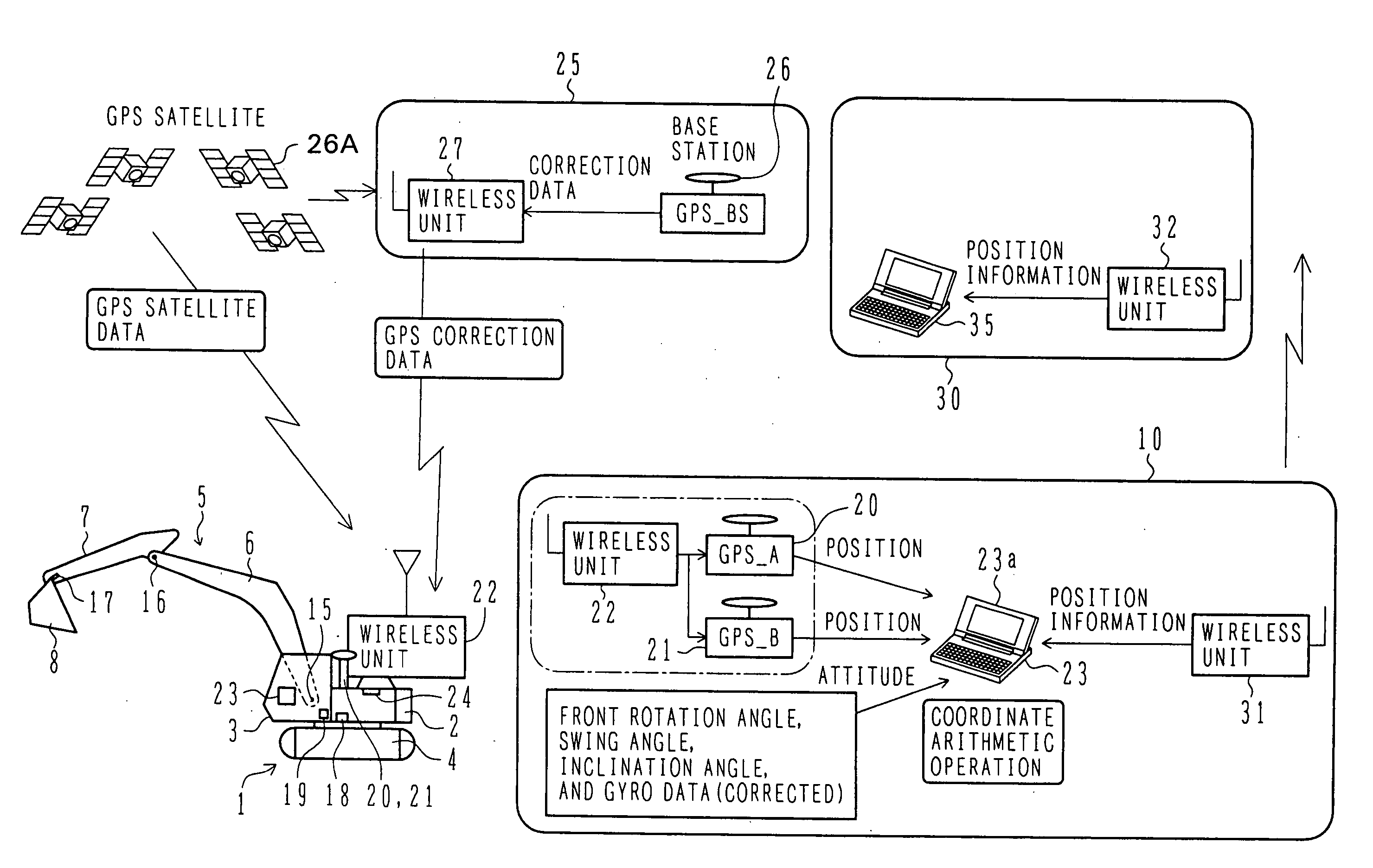
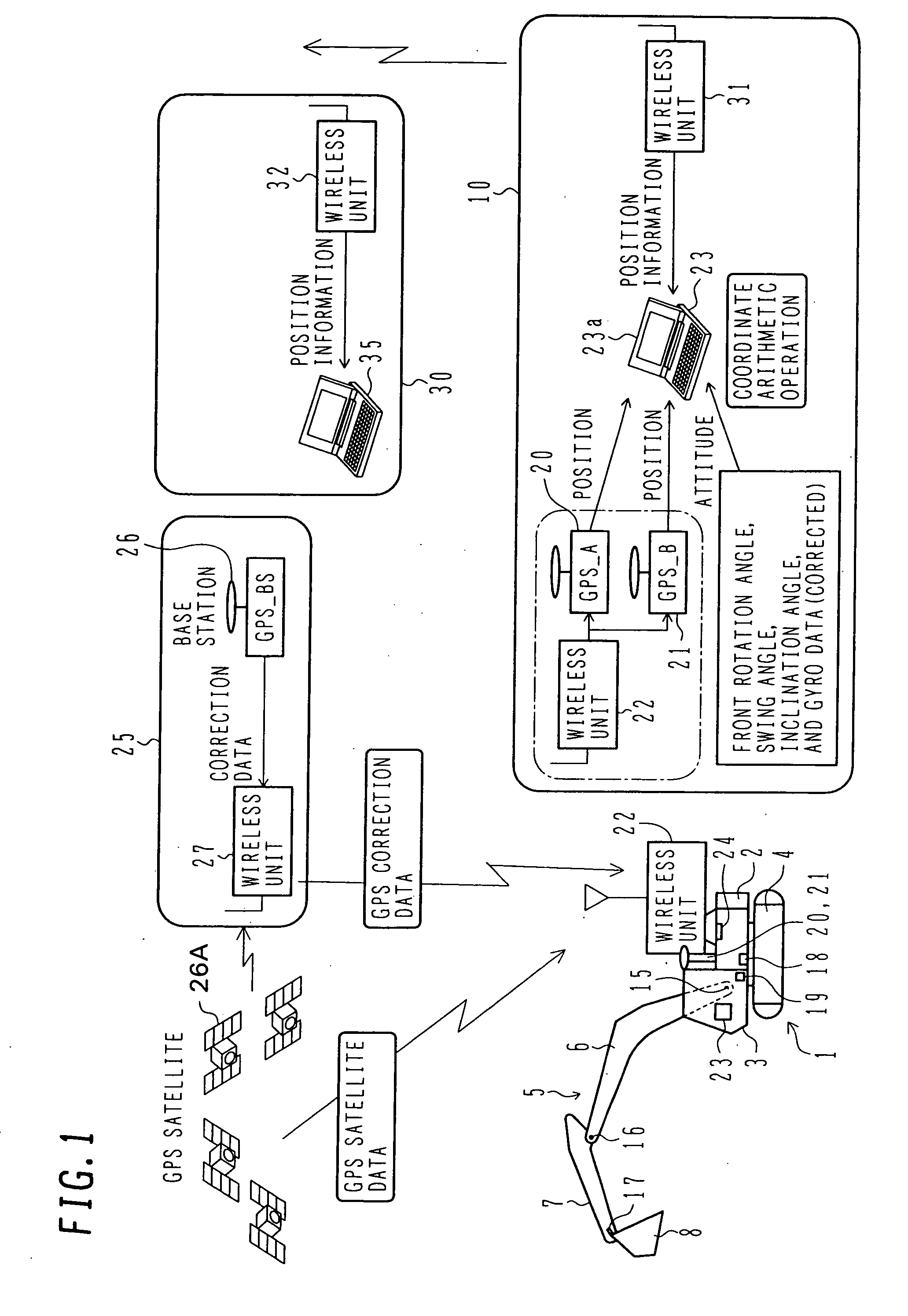
[0053]FIG. 1 is an illustration showing the overall configuration of a work support and management system in which the present invention is applied to a crawler mounted hydraulic excavator.
[0054] Referring to FIG. 1, a hydraulic excavator 1 comprises a swing body 2, a cab 3, a travel body 4, and a front operating mechanism 5. The swing body 2 is rotatably mounted on the travel body 4, and the cab 3 is located in a front left portion of the swing body 2. The travel body 4 is illustrated as being of the crawler type, but it may be of the wheel type having wheels for traveling.
[0055] The front operating mechanism 5 comprises a boom 6, an arm 7, and a bucket 8. The boom 6 is mounted to a front central portion of the swing body 2 rotatably in the vertical direction. The arm 7 is mounted to a fore end of the boom 6 rotatably in the back-and-forth direction, and the bucket 8 is mounted to a fore end of the arm 7 rotatably in the back-and-forth direction. The boom 6, the arm 7, and the bu...
second embodiment
[0095] the present invention will be described with reference to FIG. 9 through 12.
[0096]FIG. 9 is an illustration showing the overall configuration of a work support and management system according to the second embodiment when the present invention is applied to a mine sweeping machine.
[0097] Referring to FIG. 9, a mine sweeping machine 101 is constructed by using a crawler mounted hydraulic excavator as a base machine, and has the same basic structure as the hydraulic excavator shown in FIG. 1. Similar components to those in FIG. 1 are denoted by respective numerals increased by 100. However, a front operating mechanism 105 includes a rotary cutter 108 instead of the bucket, and a radar explosive probing sensor 181 is mounted to a lateral surface of an arm 107. The sensor 181 is movable along the lateral surface of an arm 107 through a telescopic extendable arm 182. Also, the sensor 181 is rotatable relative to the telescopic extendable arm 182 by a probing sensor cylinder.
[009...
third embodiment
[0124] the present invention will be described with reference to FIG. 13 through 16.
[0125]FIG. 13 is an illustration showing the overall configuration of a work support and management system according to the third embodiment in which the present invention is applied to a ground improving machine.
[0126] Referring to FIG. 13, a ground improving machine 201 is constructed by using a crawler mounted hydraulic excavator as a base machine, and has the same basic structure as the hydraulic excavator shown in FIG. 1. Similar components to those in FIG. 1 are denoted by respective numerals increased by 200. However, a front operating mechanism 205 includes, instead of the bucket, a stirrer 208 for spraying a solidifier into soft ground and stirring it.
[0127] An on-board system 210 is mounted on the ground improving machine 201, and a GPS base station 225 and a management room 230 are installed in other places. The GPS base station 225 and the management room 230 also have the same basic co...
PUM
 Abstract
Description
Claims
Application Information
 - R&D
- Intellectual Property
- Life Sciences
- Materials
- Tech Scout
- Unparalleled Data Quality
- Higher Quality Content
- 60% Fewer Hallucinations
Browse by: Latest US Patents, China's latest patents, Technical Efficacy Thesaurus, Application Domain, Technology Topic, Popular Technical Reports.
© 2025 PatSnap. All rights reserved.Legal|Privacy policy|Modern Slavery Act Transparency Statement|Sitemap|About US| Contact US: help@patsnap.com


