
Apparatus And Related Method For Calculating Parity of Redundant Array Of Disks

a parity calculation and array technology, applied in the field of apparatus and related methods for implementing parity calculation of redundant array of disks, can solve the problems of high resource demand, high heat output, high cost, etc., and achieve the effects of low resource consumption, fast and efficient hardware parity calculation, and low cos

Inactive Publication Date: 2006-02-02
VIA TECH INC
View PDF14 Cites 10 Cited by
  • Summary
  • Abstract
  • Description
  • Claims
  • Application Information

AI Technical Summary

Benefits of technology

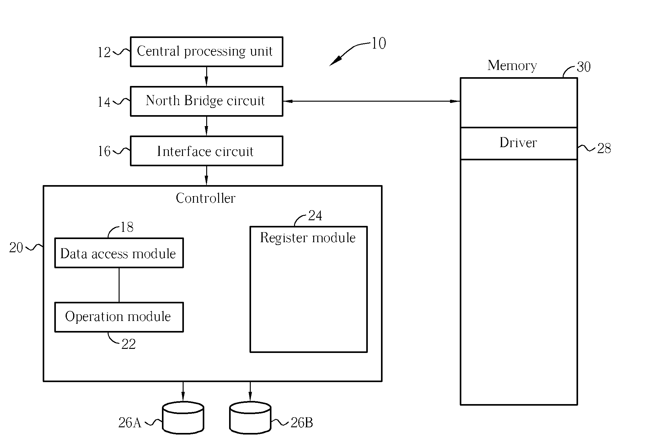
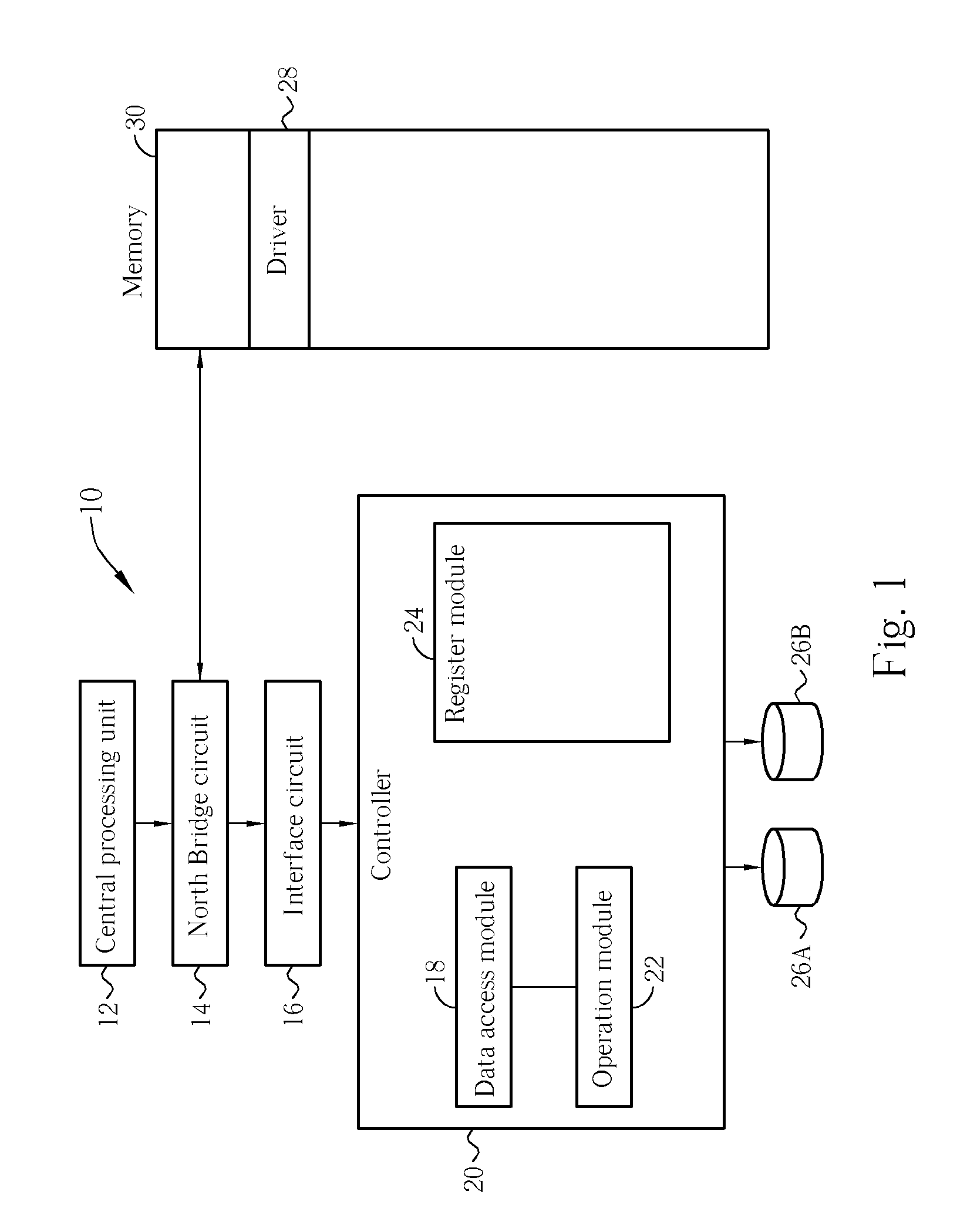
[0009] The claimed invention uses hardware of the RAID controller to perform a parity calculation, furthermore, a mechanism of the direct memory access of the RAID controller allows the RAID controller to gain direct access into the system memory to support the memory resources needed by the parity calculation. By not using the central processing unit, the claimed invention can perform the hardware parity calculation with a faster speed and a higher efficiency. Also there is no need to install a special memory and related circuit into the RAID controller. Thus in the claimed invention, the RAID controller has qualities like simplified components, low cost, low resource demand, and low heat output, and is capable of either being installed as a interface card, or built-in to motherboards or chipsets.
[0015] In performing the hardware parity calculation, the claimed invention bypasses the central processing unit as the RAID controller uses simplified, low cost, and low resource-consuming components to achieve a fast and efficient hardware parity calculation to support all related operations of the RAID.

Problems solved by technology

Thus, complicated components, high cost, high resource demand, high heat output, and a large circuit area of the RAID controller make it unsuitable for built-in motherboards and chipsets.
It is obvious that the current technology increases operation workload and hence decreases system operation efficiency.

Method used


Image

  • Apparatus And Related Method For Calculating Parity of Redundant Array Of Disks
  • Apparatus And Related Method For Calculating Parity of Redundant Array Of Disks
  • Apparatus And Related Method For Calculating Parity of Redundant Array Of Disks

Examples


first embodiment

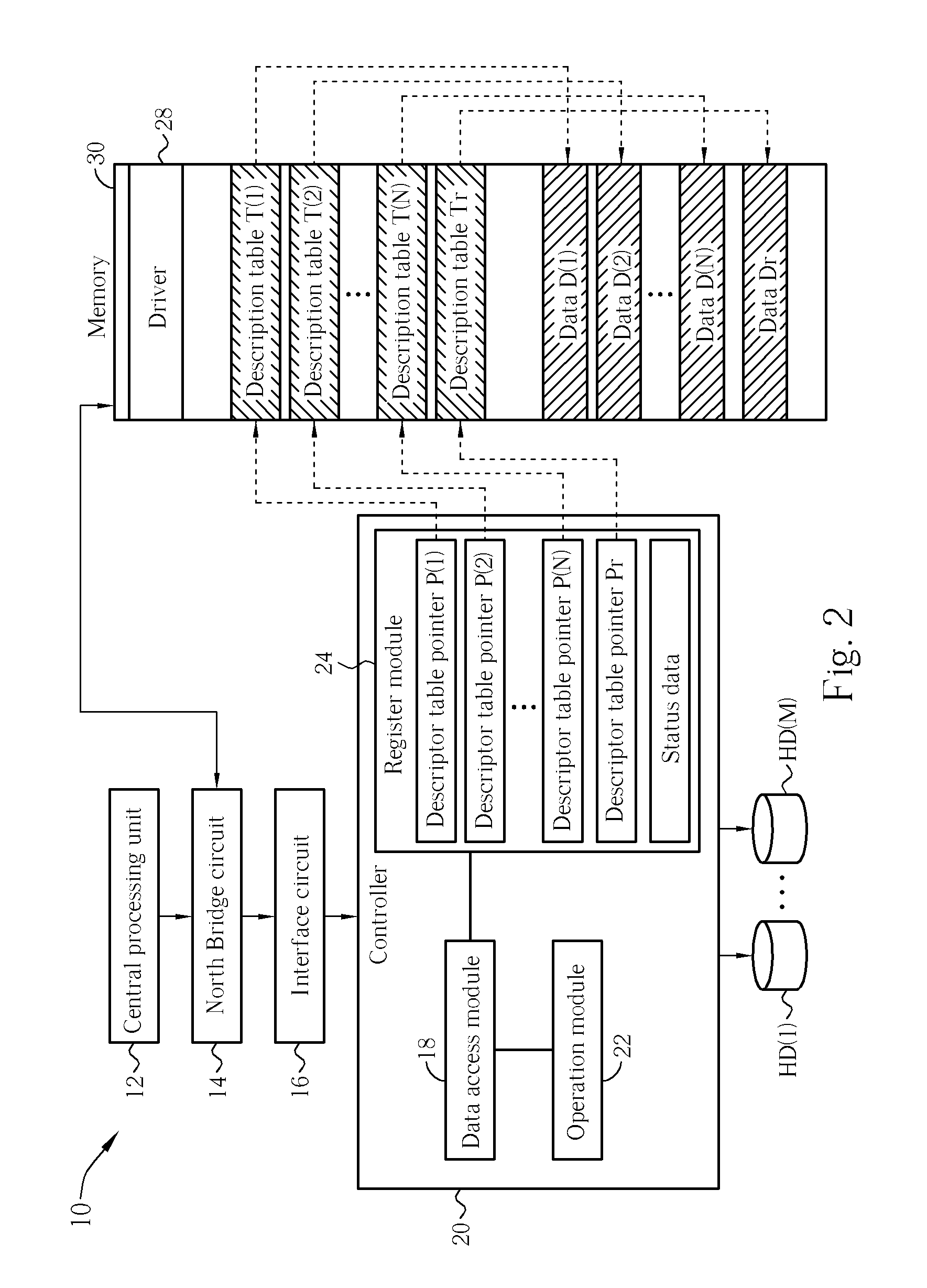
[0024] The invention has three ways to utilize the mechanism of descriptor table pointers and description tables of the direct memory access, and the mechanism of status register, to support parity calculations needed by the RAID during operation. The three examples will be explained later. Firstly, please refer to FIG. 2 (at the same time also refer to FIG. 1); FIG. 2 illustrates a diagram of how a hardware parity calculation is implemented by the computer system 10 of FIG. 1 according to the If during the operation of the RAID, the controller 20 needs to perform the hardware parity calculation on data D(1), D(2), to D(N) to generate a corresponding data Dr; then the central processing unit 12 will first prepare the input data D(1) to D(N) of the parity calculation in the memory 30, and through the execution of the driver 28, gathers the description tables T(1) to T(N1) in the memory 30 and writes each descriptor table pointer P(1) to P(N) and Pr into the register module 24 of the...

second embodiment

[0029] Please refer to FIG. 3 (at the same time also to FIG. 1). FIG. 3 illustrates a diagram of how a hardware parity calculation is implemented in the computer system 10 according to the Similar to the embodiment of FIG. 2, in the embodiment of FIG. 3, when the RAID controller 20 performs a hardware parity calculation on data D(1), D(2) to D(N), the central processing unit 12 will coordinate the execution of the driver 28 and each corresponding descriptor table pointer T(1) to T(N) and Tr and each corresponding descriptor table pointer P(1) to P(N) and Pr will be prepared in the memory 30. The difference in the example of FIG. 3 is that the register module 24 of the controller 20 only requires to realize one descriptor table pointer register and one status register, and each descriptor table pointer P(1) to P(N), Pr sequentially fills the descriptor table pointer register. This also allows the controller 20 to access each data D(1) to D(N) sequentially. For example, when the desc...

third embodiment

[0032] Please refer to FIG. 4. FIG. 4 illustrates a diagram of how a hardware parity calculation is implemented in the computer system 10 according to the Similar to the previous two embodiment, when the controller 20 performs a parity calculation on the data D(1) to D(N), the central processing unit 12 coordinates by executing the driver 28 and prepares the data D(1) to D(N) in the memory 30 and also the corresponding description tables T(1) to T(N) and Tr. Similarly, the central processing unit 12 is also required to prepare the descriptor table pointers P(1) to P(N) and Pr to indicate each descriptor table pointer in the addresses of the memory 30. The difference with the embodiment in FIG. 4 is that the descriptor table pointers P(1) to P(N) and Pr are to be stored in the memory 30 and these descriptor table pointers P(1) to P(N) are recorded as a main pointer table P0 in the address of the controller 30. Thus the main pointer table P0 is filled into the register module 24 of t...


PUM


Abstract

For error tolerance in a redundant array disks (RAID), a parity data is calculated according to plurality of data respectively accessed in disks of the RAID. A hardware calculation module for parity calculation can be implemented in a RAID controller. With direct memory access (DMA) capability of the RAID controller, the calculation module performs parity calculation by directly accessing a system memory for the plurality of data and the parity data. Thus, memory resources of the parity calculation can be supported by the system memory, and a central processing unit (CPU) can be offloaded during parity calculation.

Description

BACKGROUND OF THE INVENTION [0001] 1. Field of the Invention [0002] The invention relates to an apparatus and a related method for implementing parity calculation of a redundant array of disks (RAID), more particularly, to an apparatus and a related method for implementing a hardware calculation module for parity calculation by directly accessing a system memory. [0003] 2. Description of the Prior Art [0004] A computer system is an essential piece of hardware in modern society. In order to calculate and manage all kinds of electronic information, figures and data, all computer systems have a hard disk as a storage device for nonvolatile random access to data, documents and multimedia files. The size, speed and safety in accessing large amounts of information are the main points manufacturers are concerned with. [0005] With increasing hard disk capacity and low price, the modern computer system is capable of implementing RAID wherein multiple disks are merged to operate together, inc...

Claims


Application Information

Patent Timeline
IPC IPC(8): G06F13/36
CPCG06F13/385G06F13/28
Inventor LI, YONG
Owner VIA TECH INC
Learn More