
Piston having centered pin hole and skirt profile

a pin hole and profile technology, applied in the direction of trunk pistons, machines/engines, plungers, etc., can solve the problems of ring and liner wear, premature piston wear,

Inactive Publication Date: 2006-02-09
FEDERAL MOGUL WORLD WIDE
View PDF6 Cites 5 Cited by
  • Summary
  • Abstract
  • Description
  • Claims
  • Application Information

AI Technical Summary

Benefits of technology

"The use of a central pin and central skirt combination in a piston design has several technical benefits. These include a quieter piston, reduced stress and mass, improved land fitting, reduced friction, easier manufacturing, and improved design accuracy. Additionally, this design reduces motion change at top dead centering firing and enables a reduction in land clearance, which reduces ring side wear and microwelding."

Problems solved by technology

Pin offset produces undesirable secondary motion of the piston in operation, leading to premature piston, ring and liner wear.

Method used


Image

  • Piston having centered pin hole and skirt profile
  • Piston having centered pin hole and skirt profile
  • Piston having centered pin hole and skirt profile

Examples


Embodiment Construction

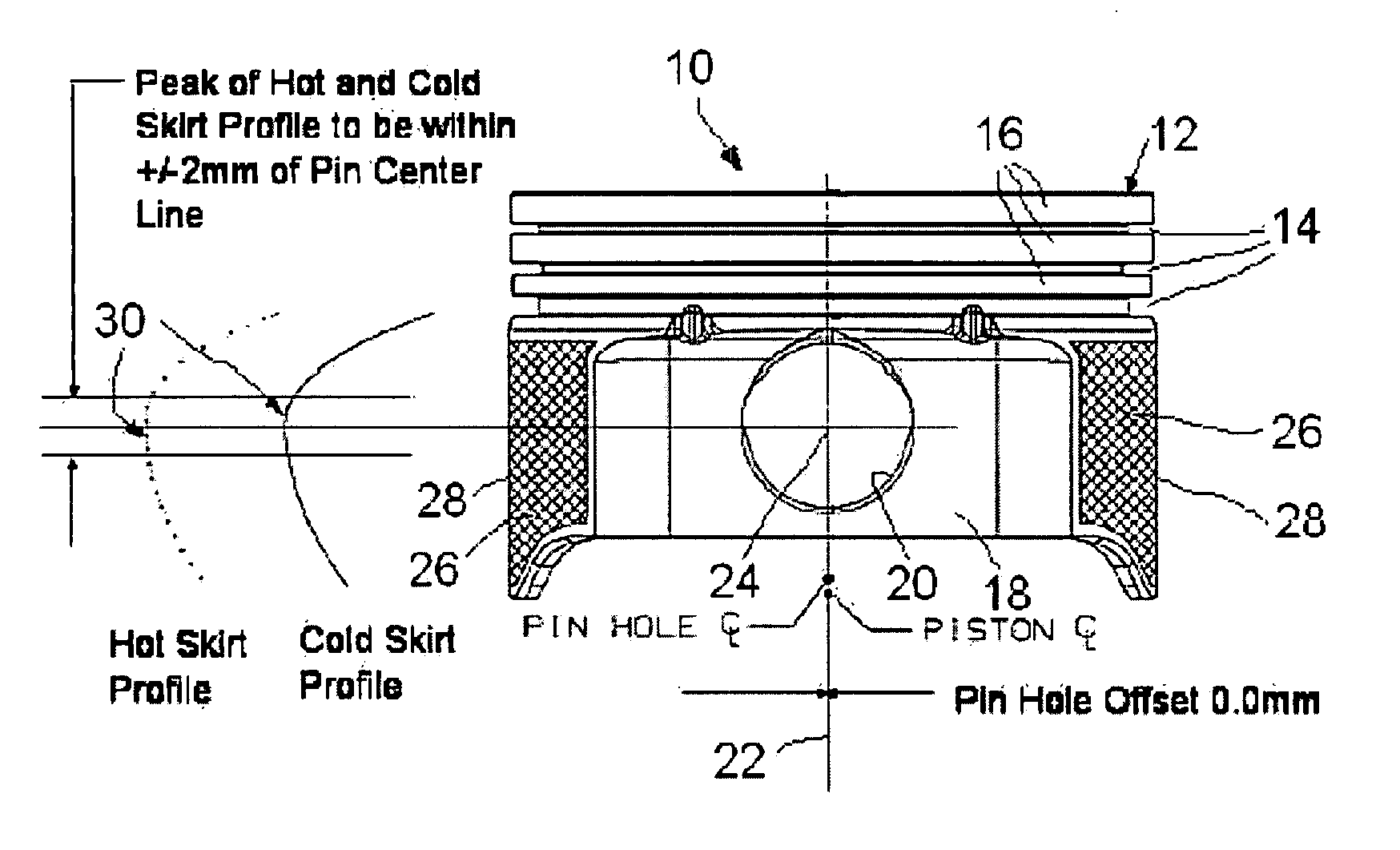
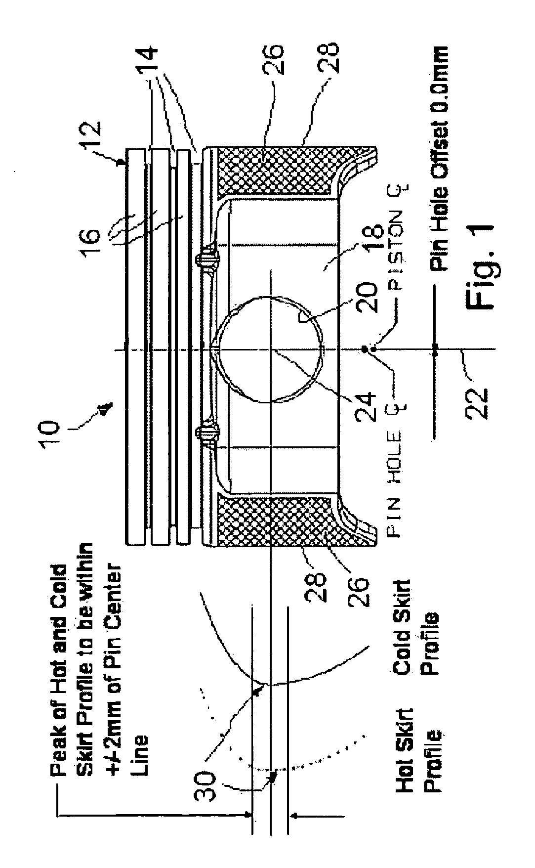
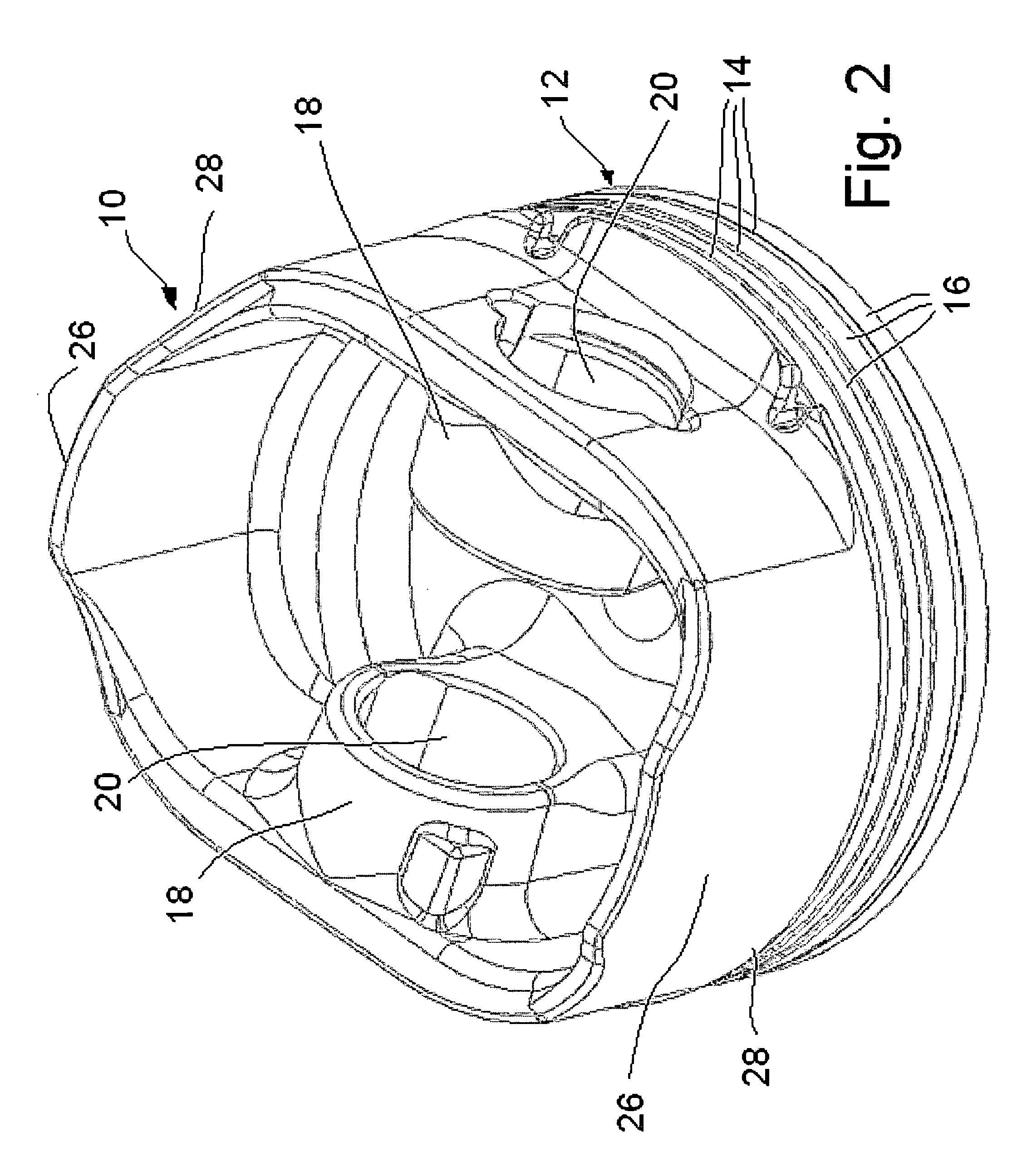
[0009] Referring to FIGS. 1 and 2, a piston 10 is shown having a head 12 formed with a plurality of ring grooves 14 for accommodating a plurality of piston rings (not shown). Between the ring grooves are lands 16. A pair of pin bosses 18 project below the head 12 and are spaced laterally from one another. The pin bosses 18 are formed with axially aligned pin bores or holes 20 for receiving a wrist pin (not shown) for attachment of the piston to a connecting rod (not shown) in conventional manner. The piston 10 has a longitudinal centerline or axis 22 which passes through the axis of the pin holes 20, such that there is no lateral offset of the pin hole axis 24 relative to the piston centerline 22.

[0010] The piston 10 includes skirt portions 26 on opposite sides of the piston 10 between the pin bosses 18. The skirt portions 26 each have an outer surface 28 with a skirt profile 30 that is convexly shaped in the longitudinal direction of the piston and skirt. The profile 30 has a majo...


PUM


Abstract

A piston includes a piston body having a longitudinal central axis. A piston head is formed with a plurality of ring grooves and a pair of pin bosses depend from the head and are formed with a pair of pin bores that are centered on a common pin bore axis that intersects the longitudinal axis of the piston. Skirt Portions have outer surfaces with a longitudinal profile that is convexly shaped. A major diameter of the profile lies within ±2 mm of the pin bore axis in both a cold and hot condition.

Description

[0001] This invention claims priority to U.S. Provisional Application No. 60 / 598,009, filed Aug. 2, 2004.1. TECHNICAL FIELD [0002] This invention relates to pistons for internal combustion engines. 2. RELATED ART [0003] Pin offset was traditionally added to pistons, in the days of the tapered skirt, to insure that the soft lower skirt would touch the cylinder bore prior to the rigged upper skirt. It has further been proposed to locate the major diameter of the skirt on the pin centerline, but in combination with the offset pin. Pin offset produces undesirable secondary motion of the piston in operation, leading to premature piston, ring and liner wear. SUMMARY OF THE INVENTION [0004] A central pin and central skirt combination is employed to produce a symmetric piston design. With this design, inertia and gas loading no longer act on the piston to produce piston secondary motion. [0005] The combination of the central pin and central skirt: 1) produces a quiet piston, 2) reduces stre...

Claims


Application Information

Patent Timeline
Patent Type & Authority Applications(United States)
IPC IPC(8): F16J1/04
CPCF16J1/16F02F3/00F16J1/00F16J1/04
Inventor MILLER, ANDREW JOHN
Owner FEDERAL MOGUL WORLD WIDE
Learn More