
Thin plate storage container

a storage container and thin plate technology, applied in the direction of containers preventing decay, packaging goods, sealing, etc., can solve the problems of slipping of the sealing member, affecting the sealing effect, so as to prevent slipping, improve sealing, and reduce the load on the container body in the conveyance

Active Publication Date: 2006-02-09
MIRAIAL CO LTD
View PDF16 Cites 9 Cited by
  • Summary
  • Abstract
  • Description
  • Claims
  • Application Information

AI Technical Summary

Benefits of technology

[0013] The aim of the present invention is to provide a thin plate storage container wherein the lid is prevented from slipping, the load on the container body in conveyance is reduced to improve sealing, and a plurality of the thin plates can be securely held within the container body.
[0018] Generation of dust and the like can be kept to the minimum because each contacting surface is planar. The material of the lid support inserts and that of the corner inserts are selected to minimize dust generation when they are rubbed by each other.
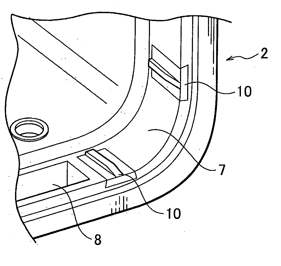
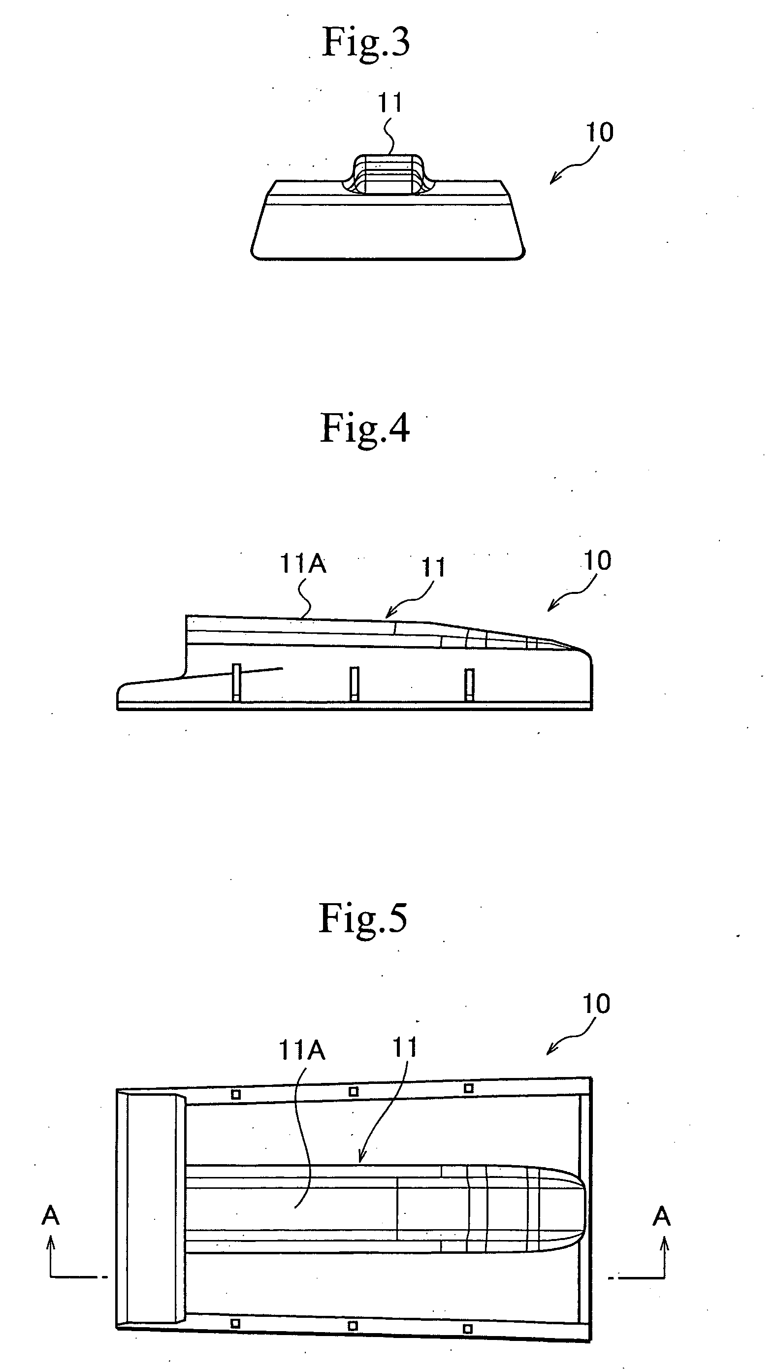
[0020] The contacting plate portion is positioned to cover a corner of the lid by insertion of the fixing plate portion into the engagement groove at the corner of the lid. Thus mounted, the planar contacting surfaces, at both ends of the contacting plate, are in contact with a lid support insert to support the lid. Thereby, the lid scarcely slips when the container body receives a shock, and sealing quality is improved.
[0022] Handles are provided on the side plates for lifting the container body. When these handles are gripped and lifted, the supporting member is held directly, with the container body supported by the base plate. Thereby, any distortion caused by lifting is absorbed by the base plate and the side plates of the supporting member, so that any ill effect on the container body is minimized.
[0023] It is preferable that detents be provided in opposing side walls of said container body so that the container body can be supported more securely by the supporting members by engagement with lugs on the opposing sidewalls of the container body with the side plates of the supporting member.

Problems solved by technology

However, since the handles are located on the sidewalls of the thin plate storage container, the sidewalls receive a load when the thin plate storage container is lifted, whereby the opening of the container body can be slightly distorted and the sealing member can slip slightly.
This effect is undesirable although there is no problem with the sealing.
Although there is no problem in normal use of the thin plate storage container, there is the possibility that the thin plate storage container will receive a shock when the thin plate storage container is mounted in use.
In this case, the lid can slip because of the gap between the container body and the lid and the sealing member will also slip.
In such an event, although there is no sealing problem, the result is not the desired perfection.
Therefore, it is difficult to securely hold a semiconductor silicon wafer 37 of a large radius and heavy weight and there is the problem that the semiconductor silicon wafers 37 shake within the container.

Method used


Image

  • Thin plate storage container
  • Thin plate storage container
  • Thin plate storage container

Examples


first embodiment

[0060] In the first embodiment, a storage container to store and transport semiconductor silicon wafers as thin plates is given as an example.

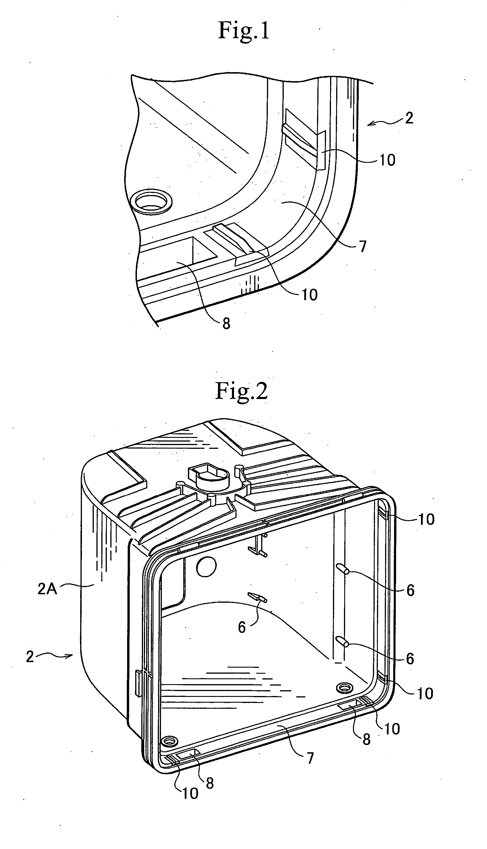
[0061] This wafer storage container 1 comprises, as shown in FIGS. 2, 9, and 13, a container body 2 for supporting a plurality of semiconductor silicon wafers (not shown), and wafer supporting plates (not shown) on the inside surface of two sidewalls inside of this container body 2 facing each other to support a plurality of semiconductor silicon wafers, stored in parallel and at regular intervals, from both sides of the wafer. A lid 3 seals the upper opening of the container body 2 and keeps the inside clean. A supporting member 4 supports the container body 2.

[0062] The container body 2 is formed generally in the shape of a cube. For supporting detachable wafer supporting plates, a plurality of supporting protrusions 6 is placed on rear side and back side, inside of sidewall portions 2A and 2B of the container body 2. A lid receptacle 7 su...

second embodiment

[0086] The second embodiment of the present invention is also illustrated, by way of example, as a storage container to store and carry thin-plate semiconductor silicon wafers (thin plates).

[0087] This wafer storage container 41 of the second embodiment, as shown in FIG. 18 and FIG. 19, comprises a container body 42 for storing a plurality of semiconductor silicon wafers (not shown) therein. Wafer support plates 43 are provided on opposite side walls in the container body 42 for supporting the semiconductor silicon wafers from opposite sides of the wafers, which are stored within the container body, in parallel and at regular intervals. Lid 44 seals the upper opening of the container body 44 and keeps the container's inside clean.

[0088] A lid receptacle 45 is provided around the opening of the container body 42 to engage the lid 44. This lid receptacle (flange) 45 is similar to flange 7 of the first embodiment and is formed by enlarging the edges of the container body 42 surroundi...


PUM


Abstract

A wafer storage container has a container body and a lid. Thin plates are inserted into and picked up from the container body. The container has lid supporters placed on a lid receptacle of the container body, and contacting portions contact with the lid supporters to support the lid. A supporting member is a member attached to support the container body. The supporting member has a base plate portion to support the container body, side plate portions formed as standing from the base plate portion, and a handle on each side plate gripped to lift the container body. The thin plate supporting member has contacting portions to support thin plates, supporting members to support the contacting portions elastically, and base supporting bar portions to support the supporting portions. Tip end of each supporting portion contacts with a contacting portion of each supporting stage, and elastically supports the contacting portions from both sides.

Description

CROSS-REFERENCE TO RELATED APPLICATION [0001] This application claims, under 35 USC 119, priority of Japanese Application No. 2002-349457 filed Dec. 2, 2002 and Japanese Application No. 2003-35062 filed Feb. 13, 2003. BACKGROUND OF THE INVENTION [0002] The present invention relates to a thin plate storage container, in which the load on the container body in transportation is reduced to improve sealing. The present invention further relates to a thin plate storage container for securely supporting a plurality of thin plates stored within the container body. [0003] The transportable containers for containing and transporting semiconductor silicon wafers are generally known. In such a wafer container, it is important to keep its inside clean to prevent dirt and the like from collecting on the surfaces of contained semiconductor silicon wafers during transportation. For this purpose, the container is sealed tightly, usually by a sealing member on the lid of the container, which sealing...

Claims


Application Information

Patent Timeline
IPC IPC(8): B65D85/48H01L21/68H01L21/673
CPCH01L21/67369H01L21/67376H01L21/67386H01L21/67383H01L21/67379H01L21/68
Inventor MATSUTORI, CHIAKIOYAMA, TAKAHARU
Owner MIRAIAL CO LTD
Learn More