
Collapsible bulk material container

a container and bulk material technology, applied in the field of shipping and storage containers, can solve the problems of bursting containers, unique packaging problems, load shifting, etc., and achieve the effect of convenient erection

Inactive Publication Date: 2006-02-09
JONES ROBERT J +1
View PDF54 Cites 40 Cited by
  • Summary
  • Abstract
  • Description
  • Claims
  • Application Information

AI Technical Summary

Benefits of technology

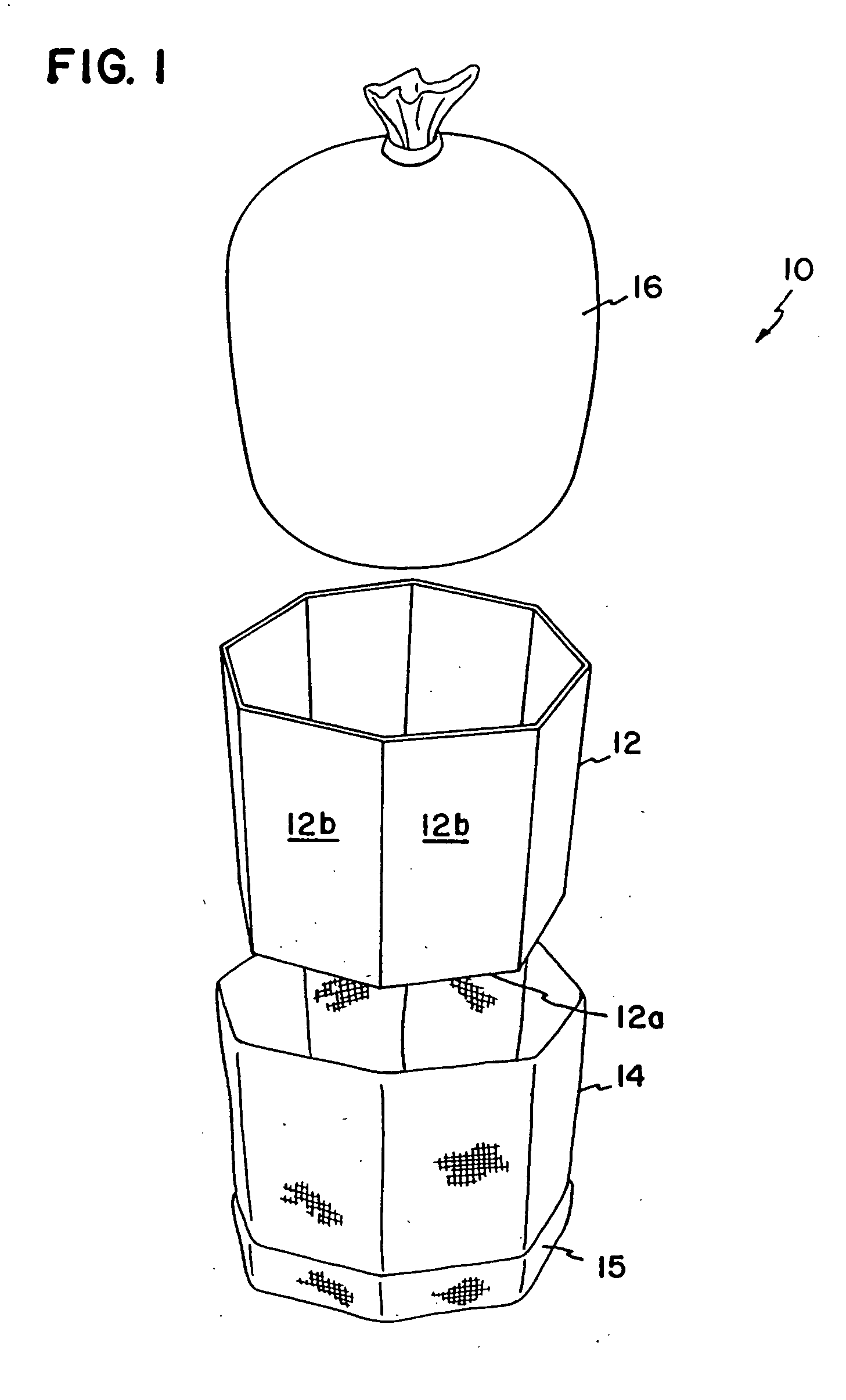
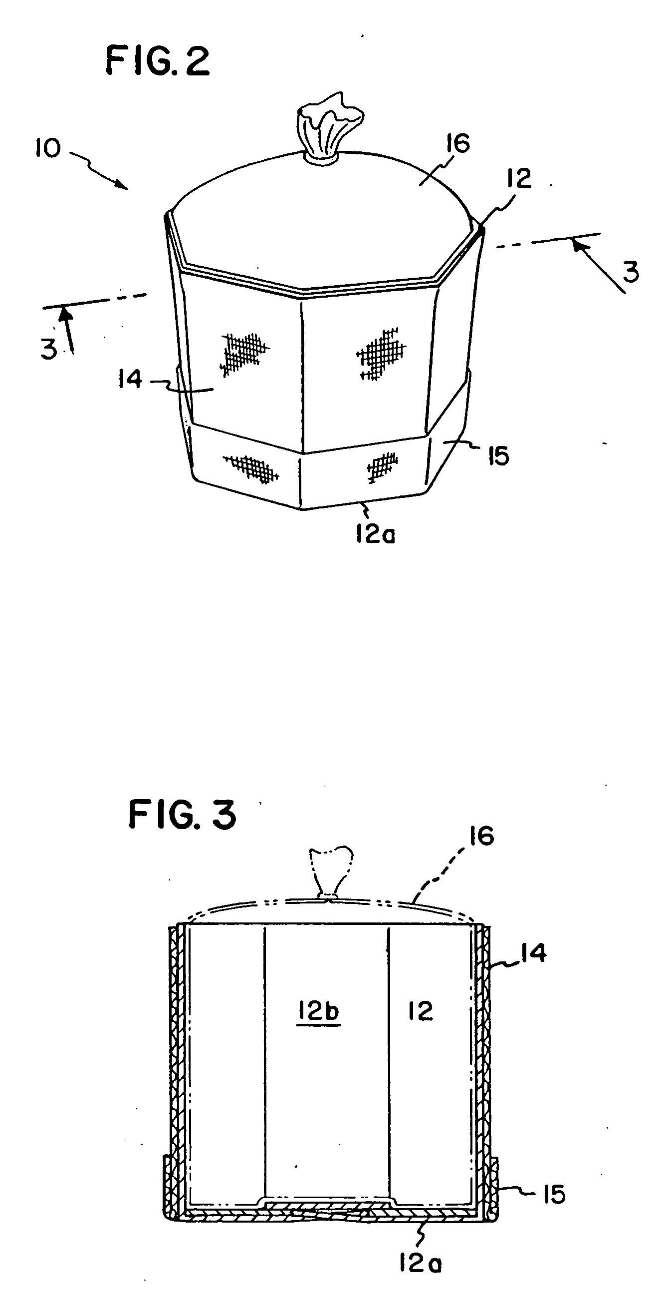
"The invention is a unique bulk container system that can be used for packaging solid, semi-solid, granular, or liquid materials. It combines the benefits of existing packaging techniques to create a cost-effective and versatile container system. The forming member is a corrugated material that provides shape and support, while the outer sleeve is made of woven polypropylene material that provides strength and can be folded for easy storage and transport. The forming member and sleeve can be collapsible for reuse and are recyclable. The container system can be adapted for different uses and has a unique design that allows for flexibility and reduced stress on the container components."

Problems solved by technology

Since such materials have a tendency to move or flow, containment of them for shipment, handling and storage raises many challenges.
The flowable nature of such products presents unique packaging issues for the container.
Movement or shifting of the materials during transport can cause deformation of the container that can result in load shifting and instability and bursting containers, often with enough force to damage or destroy the container.
The result is loss or damage to the container contents and undue cleanup and environmental concerns.
If the box board wall strength and / or thickness is reduced in order to cut costs, and a number of external support straps or bands are used, product pressure against the thinner box walls generally causes the box to bulge outwardly between the straps, resulting in a container having marginal safety factor and leading to numerous costly box failures in shipment.
Because of the cost of the manufacturing sewing operations and the cost of the rigidity enhancing inserts used in the FIBCs, they typically result in a more expensive container than their corrugated box with strapping counterparts.
Without rigid bottoms, the inserts are susceptible to significant deformation from their intended footprint configuration during loading of the FIBC, resulting in a misshaped containment system that is unstable before and during shipment.
To address this problem, collapsible metal grid cages have been configured to externally support the FIBC, further adding to the cost and use inflexibility of such systems for containing liquids or semi-liquid materials.

Method used


Image

  • Collapsible bulk material container
  • Collapsible bulk material container
  • Collapsible bulk material container

Examples


first embodiment

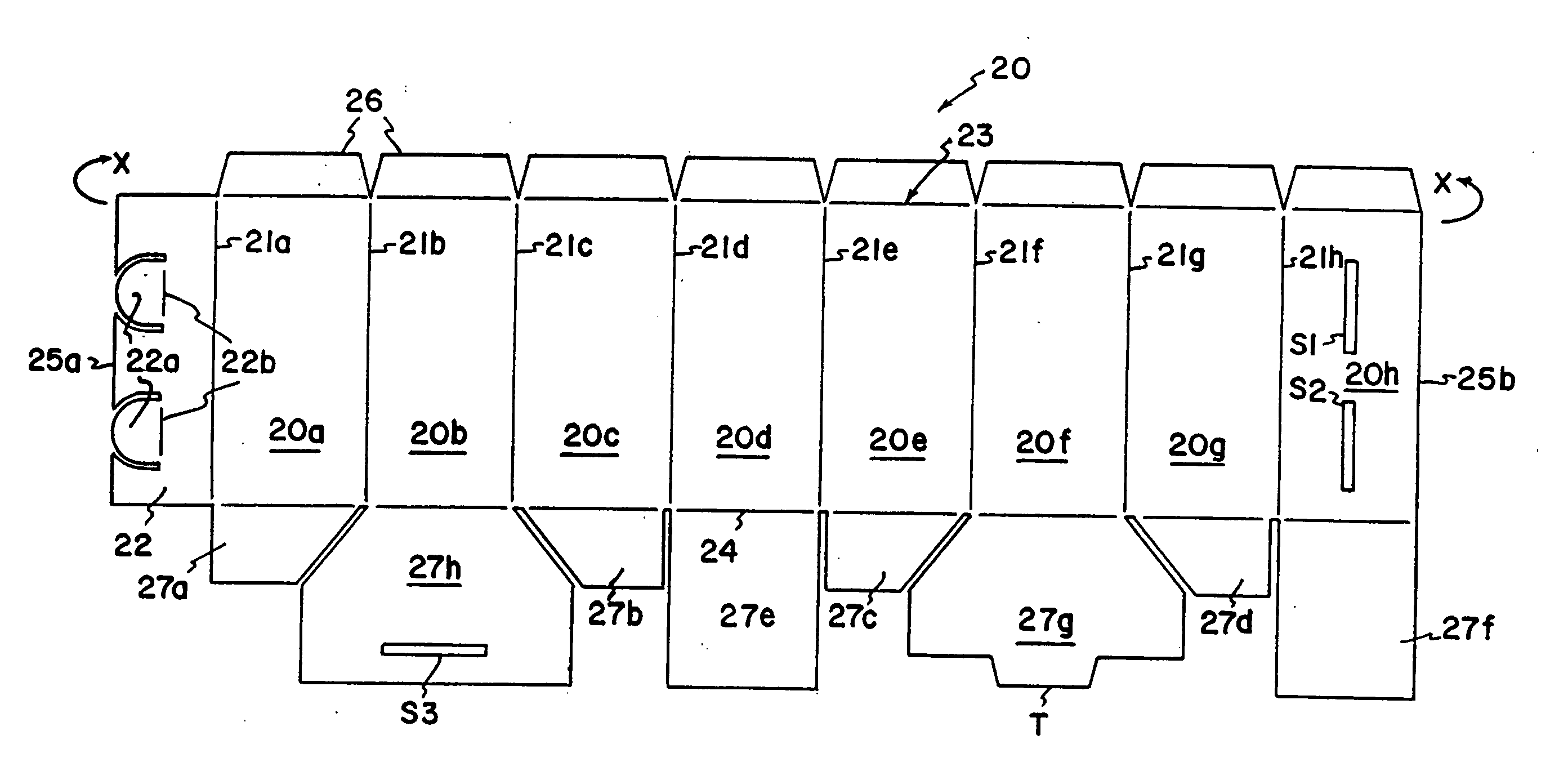
[0048] the forming member, constructed from corrugated cellulose (cardboard) material, is illustrated at 20 in FIGS. 4A-4D. In the preferred embodiment, the forming member 20 is configured from a single piece of corrugated material that is scored and patterned for folding, as illustrated in FIG. 4A. Referring thereto, the forming member 20 has eight sidewall portions 20a-20h consecutively connected and defined by intervening fold lines 21a-21h respectively, which eventually define the eight “corners” of the forming member. A connecting wall member 22 is contiguous with sidewall 20a and extends outwardly from fold line 21a. Connector wall 22 has a pair of arcuate tabs 22a cut into the wall and projecting back from the side edge 25a back to fold lines 22b. The forming member 20 also has an upper edge 23, a lower edge fold line 24 and oppositely disposed side edges 25a and 25b. Each of the sidewalls 20a-20h has a tab 26 projecting upwardly therefrom that folds along the upper edge 23 o...

second embodiment

[0055] A second octagonal embodiment of a forming member 20′ is illustrated in FIGS. 5A-5D. The general function and folding pattern of the corrugated sheet defining the forming member 20′ is basically the same as that of the forming member 20 with the following changes: (1) the uniform width dimension of the sidewalls has been changed to an irregular width pattern; (2) the upper individual tabs 26 of the forming member 20 have been replaced by a pair of elongate tabs 26′ having fold score marks 26a replacing the notched cuts of the forming member 20 pattern; and (3) the slot S3 of bottom tab 27h has been deleted in bottom tab 27h′ of the second forming member, and the lower edge of bottom 27g′ has been reconfigured to include three tabs T1, T2 and T3, separated by a pair of notches. When assembled as illustrated in FIG. 5D, the second embodiment forming member 20′ provides a more elongated octagonal structure than the regular rectangular structure of the FIG. 4 forming member.

[0056...

third embodiment

[0072] The inserts 64 and 64′ described above did not have any “bottoms”. However, the one-piece insert, constructed from corrugated cellulose (cardboard) material, which does have a bottom structure, is illustrated at 20 in FIG. 4A. In this configuration, the embodiment of the forming member, previously described and illustrated at 20 in FIGS. 4A-4D, is used as the one-piece insert, which is placed within an outer forming member 12. When so used, the insert is sized smaller than the outer forming member in order to fit within the forming member 12. This embodiment is configured and folded according to the directions given above for the embodiment of the forming member illustrated at 20 in FIGS. 4A-4D.

[0073] The one-piece insert configurations described above are by no means exhaustive of the configurations that are possible. Depending upon the forming member configuration utilized, the insert should be accordingly shaped and configured to fit within the forming member. While severa...


PUM


Abstract

A container assembly for bulk materials and a kit for assembling same are disclosed. A forming member having a plurality of sidewalls defines an internal cavity for receiving bulk materials. The sidewalls are arranged relative to one another and are locked into position so as to define a geometric volume of predetermined shape, by means of a locking assembly. The locking assembly can be integrally attached to or can be separable from the sidewalls, and can form a bottom of the container assembly. A tubular sleeve of continuous material is sized to snugly engage and overlie substantially the entire outer surface area of the sidewalls. The sleeve provides the containment strength, while the forming member provides structural shape and stability to the container assembly. Additional layers of corrugated material or woven polypropylene material or their combination may be used as inserts engaging the inner peripheral sidewall areas of the forming member to provide additional strength to the container assembly. The forming member sidewalls may be freely slidable relative to one another or may be slidably affixed to one another by releasable glue.

Description

[0001] This is a Continuation-in-Part of U.S. patent application Ser. No. 09 / 351,389, filed Jul. 13, 1999.FIELD OF THE INVENTION [0002] This invention relates generally to shipping and storage containers, and more particularly to a container for bulk, liquid and granular materials, which is collapsible and / or reusable or recyclable. BACKGROUND OF THE INVENTION [0003] Effective, reliable, safe and economical packaging of bulk products for handling, transport and storage has been a concern for many years. Bulk products requiring such packaging vary widely from semi-solids such as meat and other such food items; to granular materials such as beans, peas, grains, rice, salt, flour, sugar, dry chemicals, dry cementious products, animal feeds, fertilizers, etc.; to liquid materials such as syrups, milk, juices, glues, inks, resins, paints, chemicals, and the like. Since such materials have a tendency to move or flow, containment of them for shipment, handling and storage raises many chall...

Claims


Application Information

Patent Timeline
Patent Type & Authority Applications(United States)
IPC IPC(8): B65D5/10B65D5/56B65D5/02B65D77/06
CPCB65D5/029B65D5/10B65D77/062B65D5/445B65D77/061B65D5/42
Inventor JONES, ROBERT J.JONES, MICHAEL R.
Owner JONES ROBERT J
Learn More