Silver discharge device

a technology of silver discharge and silver slivers, which is applied in the direction of lap-winding devices, transportation and packaging, textiles and paper, etc., can solve the problems of high equipment cost of the system, and achieve the effect of reducing equipment expenditure and simplifying sliver processing

Inactive Publication Date: 2006-02-09
TRUETZSCHLER GMBH & CO KG
View PDF52 Cites 18 Cited by
  • Summary
  • Abstract
  • Description
  • Claims
  • Application Information

AI Technical Summary

Benefits of technology

[0007] Sliver processing can be simplified considerably due to the fact that the deposited sliver (sliver bundle) as such can be moved during the sliver deposit with mechanical means within the depositing region, as well as out of the depositing region following the sliver deposit. Also, the removal of the slivers from cans or the like at the downstream-connected processing mac

Problems solved by technology

One disadvantage of the device is the high equipment cost for the system.
Added to the expense for the structural adaptation of the machine to the can and the handling inv

Method used


Image

  • Silver discharge device
  • Silver discharge device
  • Silver discharge device

Examples


Embodiment Construction

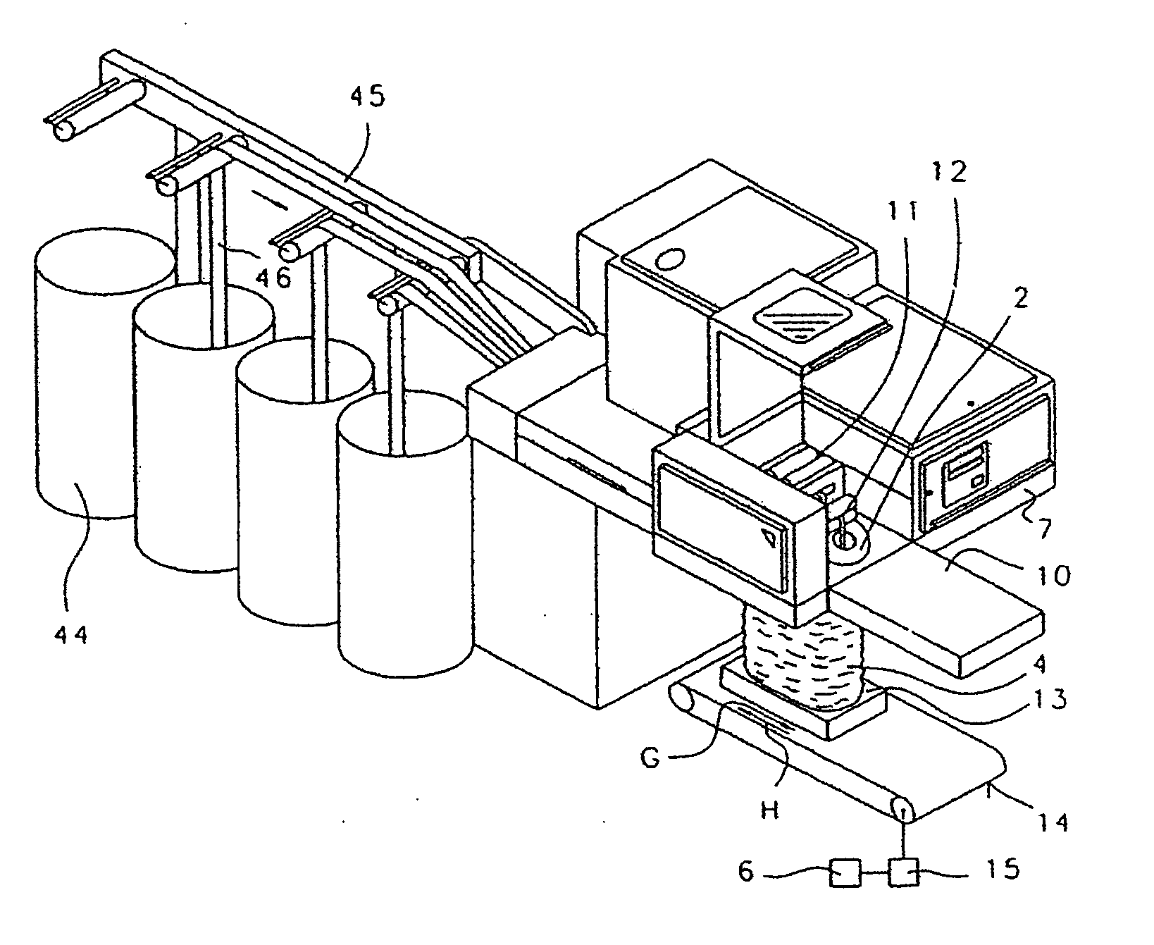
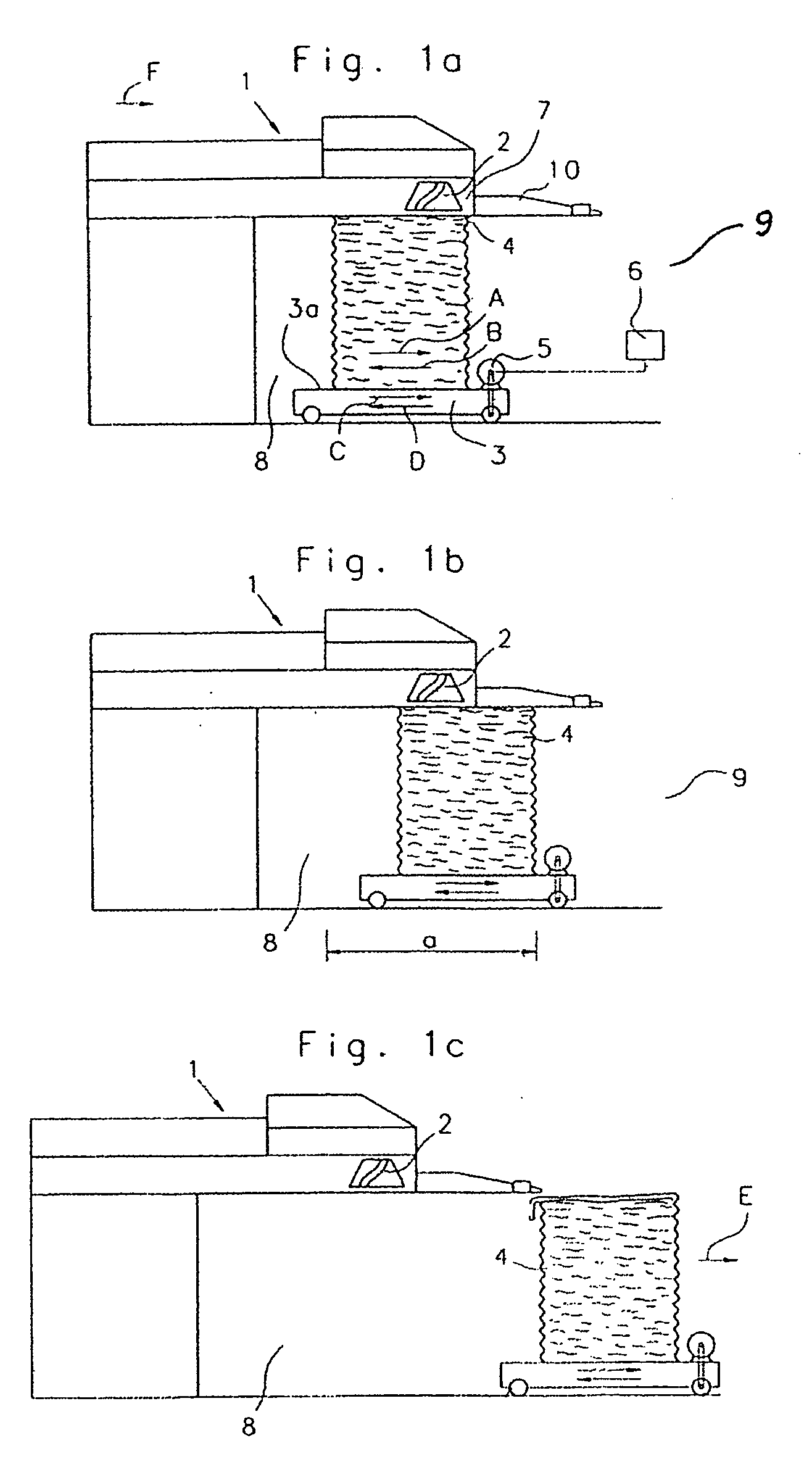
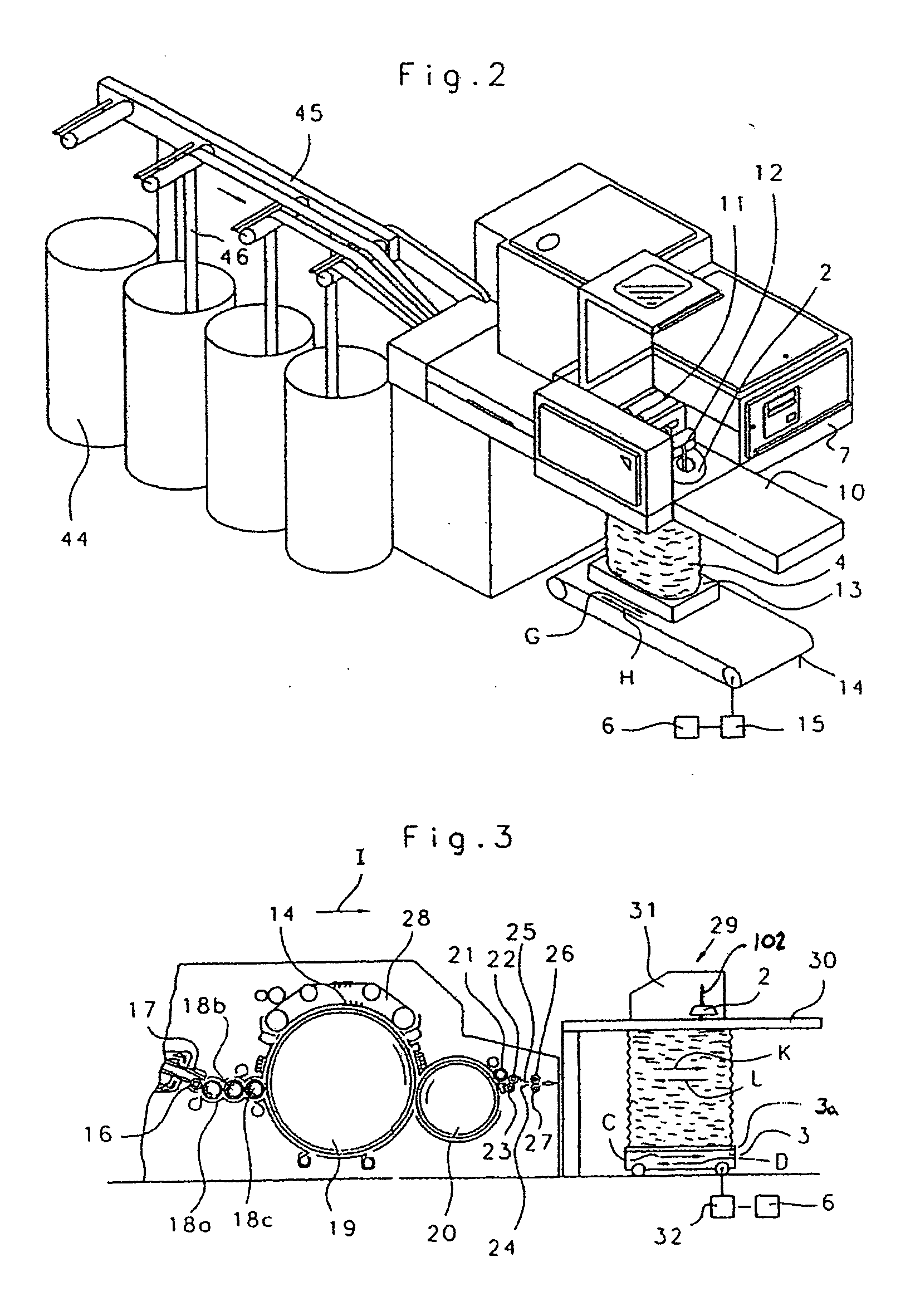
[0020]FIG. 1 shows an example of a high-performance draw frame 1 (autoleveller) manufactured by the company Trützschler, Mönchengladbach, Germany, such as the high-performance draw frame HSR 1000, in a schematic side elevation view. Individual slivers are fed from a can into the drawing unit that is not shown herein. In this unit, the slivers are drawn and combined to form a single sliver, which exits the unit. The sliver then passes through a rotating plate 2 and is subsequently deposited as a ring-shaped sliver bundle 4 on a support, for example a carriage 3 with rectangular top surface 3a, which moves back and forth in the direction of arrows A and B. In this example, the rotating plate 2 rotates about fixed axis 102. The carriage 3 is operated with a controllable drive motor 5, which is connected to an electronic control and regulating device 6, for example a machine control. A cover plate 10 for the sliver depositing device (sliver coiler arrangement) is attached to a support p...


PUM

PropertyMeasurementUnit
Lengthaaaaaaaaaa
Speedaaaaaaaaaa
Shapeaaaaaaaaaa

Abstract

A device is provided on a spinning preparation machine for receiving a sliver from a discharge device of the spinning preparation machine and transporting the sliver to a downstream machine, the spinning preparation machine having a depositing region. The device has a support for receiving the sliver deposited from the discharge device in the depositing region, and a moving device for moving the deposited sliver relative to the discharge device in the depositing region for forming a free standing sliver bundle, and for moving the free standing sliver bundle out of the depositing region for transport to a downstream machine.

Description

CROSS-REFERENCE TO RELATED APPLICATION [0001] This application is a continuation-in-part of U.S. patent application Ser. No. 10 / 350,016, filed Jan. 24, 2003, which claims priority to German Patent Application No. 102 05 061.9, filed Feb. 7, 2002, the priority of which is claimed herein. The contents of the foregoing applications are incorporated by reference in their entirety.BACKGROUND OF THE INVENTION [0002] The invention relates to a device on a spinning preparation machine, for example a carding machine or draw frame, involving the discharge of a sliver with a discharging device and depositing of the sliver on a support. The discharge device and the support can be moved relative to each other and the sliver (sliver bundle) deposited on the support can be fed to a processing machine downstream. [0003] In a known device shown in European Patent Document EP 0 457 099, a sliver produced by a sliver delivery machine (a carding machine or draw frame) is deposited in a spinning can wit...

Claims


Application Information

Patent Timeline
IPC IPC(8): B21C47/10B65H54/80D01G27/00B65H67/04D01H9/02D01H9/18D01H13/00
CPCB65H54/74B65H54/80B65H67/0428B65H2701/31D01H9/185D01G27/00D01H9/005D01H9/008D01G23/00
Inventor SCHLICHTER, STEFAN
Owner TRUETZSCHLER GMBH & CO KG
Why Eureka
Try Eureka