Light-emitting diode lamp

a technology of light-emitting diodes and led lamps, which is applied in the direction of basic electric elements, electrical appliances, and semiconductor devices, can solve the problems of deteriorating the optical characteristics of the light emitted from the lens, easy breakage of the lens part, and inability to use the lamp, so as to achieve excellent brightness characteristics of the light, long-term reliability of the led lamp, and high optical characteristics of the light emitted

Inactive Publication Date: 2006-02-09
CITIZEN ELECTRONICS CO LTD
View PDF16 Cites 73 Cited by
  • Summary
  • Abstract
  • Description
  • Claims
  • Application Information

AI Technical Summary

Benefits of technology

[0015] The object of the present invention is to provide an LED lamp capable of protecting a lens part of a translucent sealing plate, and achieving high optical characteristics of the light emitted from the lens part, excellent brightness characteristics of the light, and long-term reliability of the LED lamp.
[0016] To accomplish this object, according to one embodiment of the present invention, the LED lamp comprises a circuit board including electrode patterns, a light emitter provided on the circuit board, a reflective frame disposed on the circuit board and having a reflecting surface formed to surround the light emitter, a translucent sealing plate provided on an upper surface of the reflective frame, above the light emitter, and including a lens part, and a protecting member disposed on a periphery of an emission area of the translucent sealing plate and configured to protect the lens part of the translucent sealing plate. Therefore, the translucent sealing plate, in particular the lens part provided on the translucent sealing plate, is effectively protected by the protecting member.

Problems solved by technology

However, in each of the conventional LED lamps described above, the lens part of the translucent sealing plate is exposed outside the LED lamp, so that the lens part is easily broken by mechanical impact due to contact with the exterior.
When the lens part is broken, the problems arise that the LED lamp cannot be used or that there is a deterioration in the optical characteristics of the light emitted from the lens.

Method used


Image

  • Light-emitting diode lamp
  • Light-emitting diode lamp
  • Light-emitting diode lamp

Examples


first embodiment

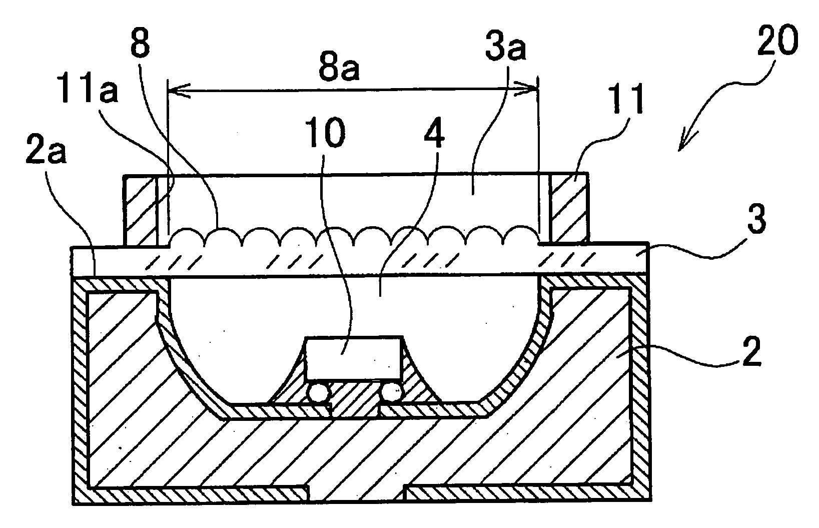
[0031]FIG. 1 shows an LED lamp 20 according to a first embodiment of the present invention. The LED lamp 20 includes a circuit board 2 and a light emitter 10 mounted on the circuit board 2. The circuit board 2 in this embodiment is formed by the same method as a three-dimensional shaped circuit component (Molded Interconnection Device) in which a board, and a conductive circuit and electrodes provided on the board (not illustrated) are integrally formed.

[0032] Hereinafter, the circuit board will be referred to as an MID board.

[0033] The light emitter 10 comprises at least one LED element in this embodiment.

[0034] The MID board 2 has a concave portion 4, and the LED element 10 is disposed on a bottom surface of the concave portion 4 through a suitable connecting mechanism so as to be connected with the electrodes provided on the circuit board.

[0035] A translucent sealing plate 3 for covering the LED element 10 is disposed on an upper surface 2a of the MID board 2, and the translu...

second embodiment

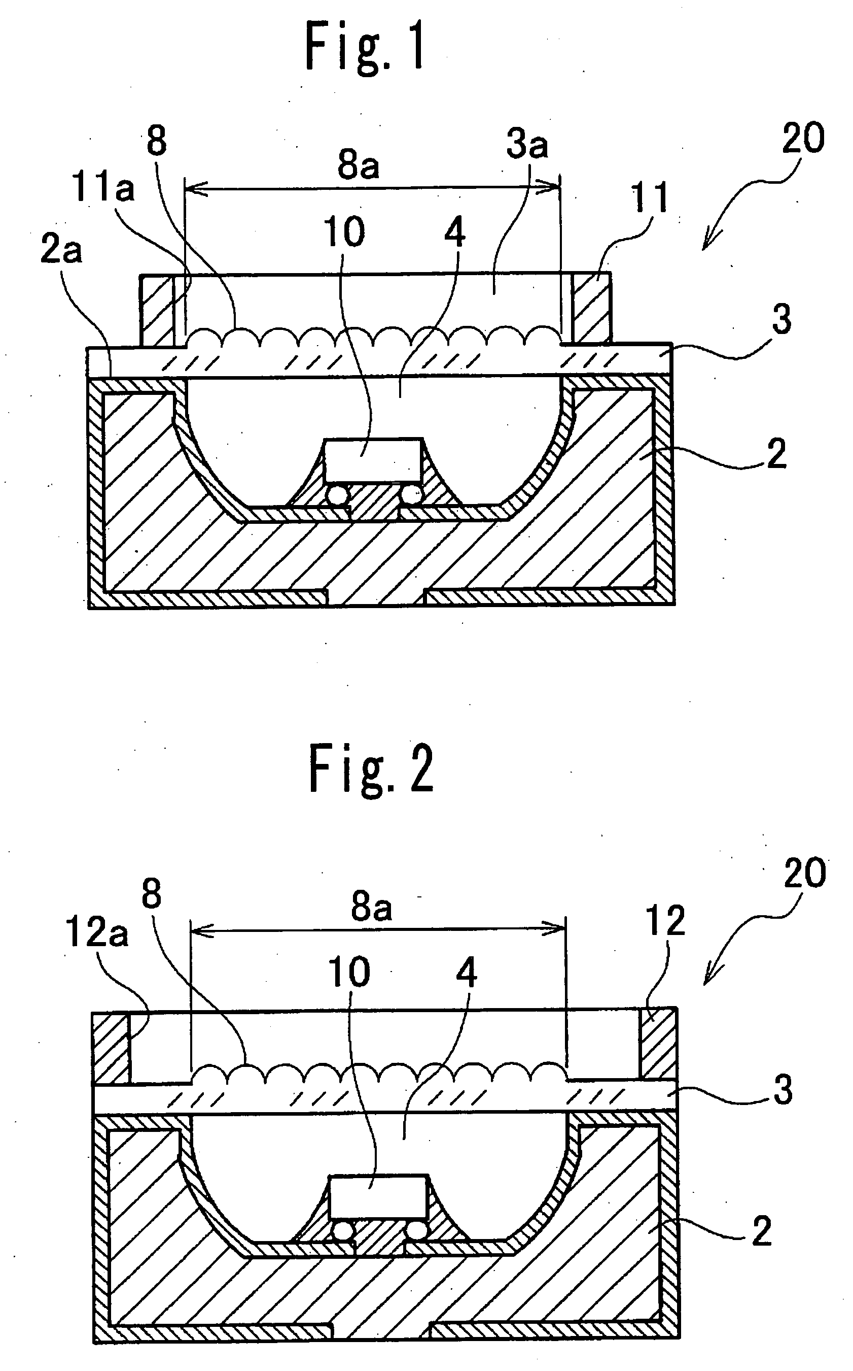
[0042] In an LED lamp according to a second embodiment of the present invention, a protecting member differs in structure from that in the first embodiment, but in other aspects it is the same as the LED lamp in the first embodiment. Therefore, the same reference numbers are attached to the parts which are identical to those in the first embodiment, and a description thereof is omitted.

[0043] The LED lamp according to the second embodiment is described below, referring to FIG. 3.

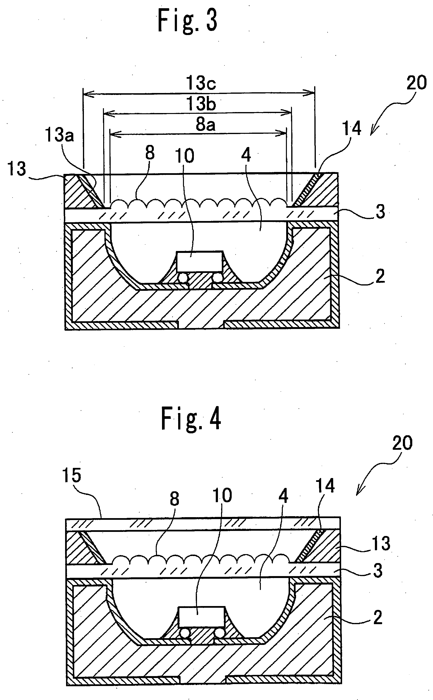
[0044] As shown in FIG. 3, an inner diameter of an opening 13a of the protecting member 13 of the LED lamp 20 in the second embodiment is set to become gradually larger from one surface adjacent to the translucent sealing plate 3 toward the other surface of the protecting member opposing the one surface. In other words, the opening 13a of the protecting member 13 has a smaller diameter 13b adjacent to the translucent sealing plate 3 and a larger diameter 13c away from the translucent sealing plate 3. The o...

third embodiment

[0049] An LED lamp according to a third embodiment of the present invention has a structure in which a translucent protecting plate is provided on an upper surface of the protecting member 13, but in other aspects it is the same as the LED lamp in the second embodiment. Therefore, the same reference numbers are attached to the parts which are identical to those in the second embodiment, and a description thereof is omitted.

[0050] The LED lamp according to the third embodiment is described below, referring to FIG. 4.

[0051] As shown in FIG. 4, the LED lamp 20 according to the third embodiment includes a translucent protecting plate 15 provided on an upper surface of the protecting member 13. The translucent protecting plate 15 is made of a sheet-like or flat plate-like acrylic, a translucent resinous material of polycarbonate or the like, or glass material, and the translucent protecting plate 15 is formed integrally with the upper surface of the protecting member 13.

[0052] Meanwhi...


PUM


Abstract

An LED lamp (30) comprising a circuit board (22) on which electrode patterns are formed, a reflective frame (31) provided on the circuit board (22) and having a concave portion (32), a light emitter (27) mounted in the concave portion (32), a translucent sealing plate (3) disposed on an upper surface of the reflective frame (31) above the light emitter (27) and including a lens part (8), and a protecting member (11) disposed on a surface having an emission area of the translucent sealing plate (3) and protecting the lens part (8), the protecting member (11) including an opening (11a) having an axis extending in a direction of thickness of the protecting member, an inner edge of the opening (11) being set to lie at an outer peripheral portion of a lens effective diameter (8a) of the lens part (8) or outside the lens effective diameter (8a).

Description

CROSS-REFERENCE TO THE RELATED APPLICATION [0001] This application is based on and claims priority from Japanese Patent Application No. 2004-230104 filed on Aug. 6, 2004, the disclosure of which is incorporated herein by reference in its entirety. BACKGROUND OF THE INVENTION [0002] 1. Field of the Invention [0003] The present invention relates to a light-emitting diode (LED) lamp, more specifically to an LED lamp configured to protect a lens for focusing, dispersing or the like of light emitted from a light emitter. [0004] 2. Description of Related Art [0005] An LED lamp is widely used in mobile terminals, home appliances, lighting, vehicles, automatic dispensers or the like. An LED lamp in which light emitted from a light emitter is emitted through a lens to the outside is well known as a first example of a conventional LED lamp (for example, see Japanese Patent Application Laid-Open Disclosure Number 2004-327955, paragraph 0029, FIG. 9). [0006]FIG. 11 illustrates the first example...

Claims


Application Information

Patent Timeline
Patent Type & Authority Applications(United States)
IPC IPC(8): H01L33/00H01L33/48H01L33/50H01L33/58H01L33/60H01L33/62
CPCH01L25/0753H01L33/483H01L2224/73204H01L33/56H01L33/58H01L33/54
Inventor KIKUCHI, SATORU
Owner CITIZEN ELECTRONICS CO LTD
Why Eureka
Try Eureka