Extended range RFID system

a rfid system and extended range technology, applied in the field of rfid systems, can solve problems such as severe limitations in the range, and achieve the effect of increasing the range of disc-type rfid systems

Inactive Publication Date: 2006-02-09
AVERY DENNISON CORP
View PDF9 Cites 90 Cited by
  • Summary
  • Abstract
  • Description
  • Claims
  • Application Information

AI Technical Summary

Benefits of technology

[0004] Accordingly, a principal object of the present inventi...

Problems solved by technology

However, the disclosed device includes a central conductive area spaced apart from the normal conductive area by a narrow...

Method used


Image

  • Extended range RFID system
  • Extended range RFID system
  • Extended range RFID system

Examples


Embodiment Construction

[0034] Before describing the drawing figures, certain background information will be noted. Specifically, the well-known relationship between frequency and wavelength may be noted as follows:

L=c / F   (1)

F=c / L   (2)

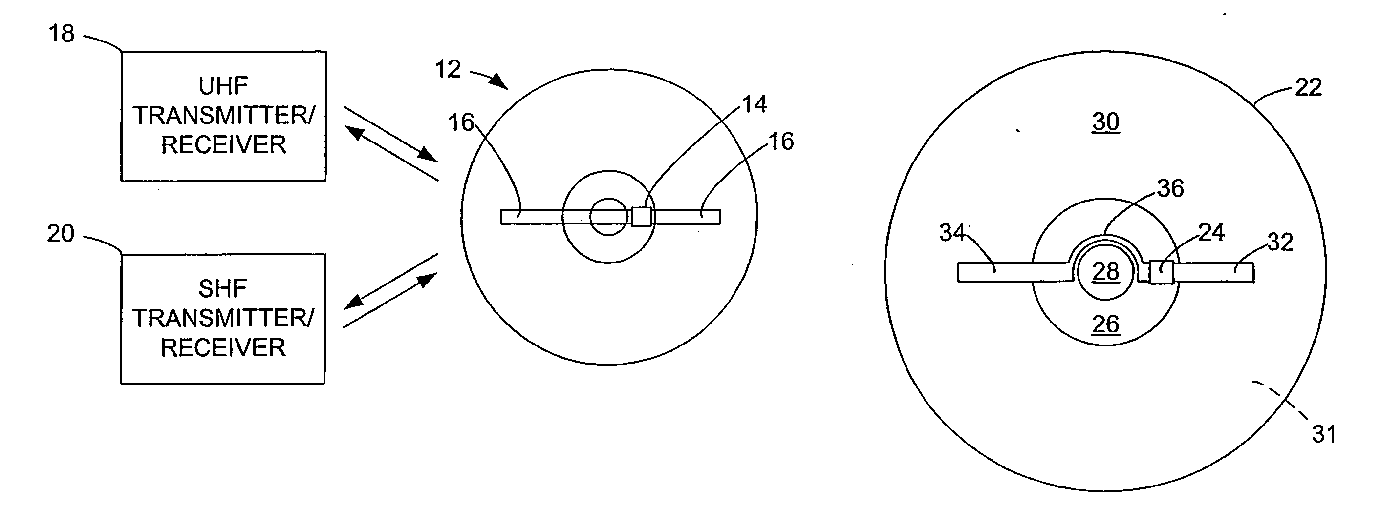
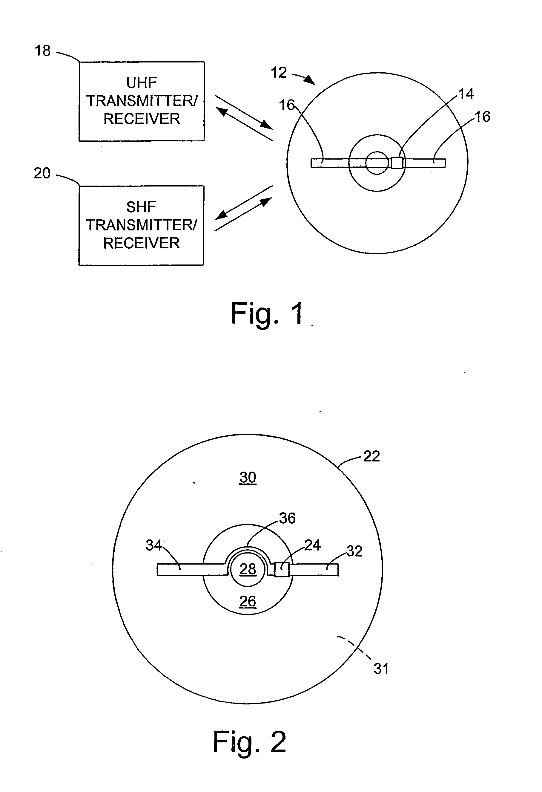
where L is the wavelength, c is the speed of light or electrical signals, equal to about 3×10¹⁰ centimeters per second, and F is the frequency. Using formula (1) set forth above, with a frequency of 915 MHz, the wavelength is approximately 32.78 centimeters (cm) and a half wavelength is about 16.4 cm. With a frequency of 2.45 GHz, or 2.45×10⁹ Hertz, the wavelength is about 12.2 cm, and the half wavelength is about 6.1 cm. Incidentally, the frequency range of from 860 to 960 megahertz is often referenced as the UHF frequency band, and the frequency range of from 2.4 to 2.5 gigahertz or 2.4 to 2.5×10⁹ Hertz is often referred to as the super high frequency (SHF) band.

[0035] It is also noted that RFID systems generally are known, and RFID transponder units are widely avail...


PUM


Abstract

A radio frequency identification (RFID) system for discs such as CDs, DVDs or minidiscs includes a special RFID transponder and antenna configuration. The discs normally include an outer metallized annular zone where information is stored, a central hole, and an inner annular zone between the hole and the outer annular zone. The transponder may be located in the inner annular zone, with antenna elements coupled to the transponder extending in opposite directions part way across the outer annular zone. Multilayer labels with a recess for the transponder chip, and antenna elements formed by conductive material may be employed to apply the RFID assembly to the discs. A monopole or dipole mode of antenna operation, prominently involving the metallized disc layer, results from the antenna configuration, and serves to more than double the range of the system.

Description

[0001] This is a continuation of International Application No. PCT / US04 / 12328, filed Apr. 25, 2004, published in English as WO 2004 / 097731. The above application is hereby incorporated by reference in its entirety.TECHNICAL FIELD OF THE INVENTION [0002] This invention relates to RFID systems, primarily for use with Compact Discs (CDs), Digital Versatile or Video Discs (DVDs) or Mini Discs. BACKGROUND OF THE RELATED ART [0003] It has previously been proposed to use Radio Frequency Identification (RFID) transponders with CDs or DVDs, and U.S. Patent Publication No. US2002 / 0175818A1 discloses such a device in FIGS. 18 and 19. However, the disclosed device includes a central conductive area spaced apart from the normal conductive area by a narrow peripheral slot, so that the primary antenna configuration is that of a fairly small slot antenna, with severely limited range. The configuration also employs conducting tabs which extend to the periphery of the disc, but the predominant radiat...

Claims


Application Information

Patent Timeline
IPC IPC(8): G08B13/14G06K19/06H01Q7/00
CPCG06K19/041G06K19/045G08B13/2417H01Q9/285H01Q1/22H01Q1/2225G08B13/2445
Inventor FORSTER, IAN J.
Owner AVERY DENNISON CORP
Why Eureka
Try Eureka