Flat display module

Inactive Publication Date: 2006-02-09
INNOCOM TECH SHENZHEN +1
View PDF3 Cites 12 Cited by
  • Summary
  • Abstract
  • Description
  • Claims
  • Application Information

AI Technical Summary

Benefits of technology

[0011] The present invention flat display module has a fixing mechanism comprising a top fixing surface, a bottom fixing surface, and a fixing sidewall, which form a fixing cavity to fix a light guide plate and an optical film. Furthermore, the fixing mechanism comprises a panel-fixing fragment f

Problems solved by technology

This limits the size and design of the end products, such as cell phones, DSC, DVC and PDAs.
As mentioned above, how to improve the design of

Method used


Image

  • Flat display module
  • Flat display module
  • Flat display module

Examples


Example

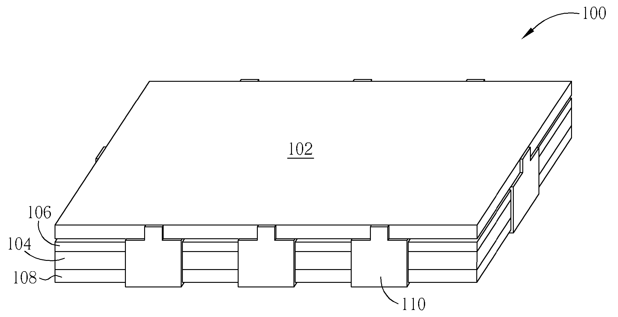
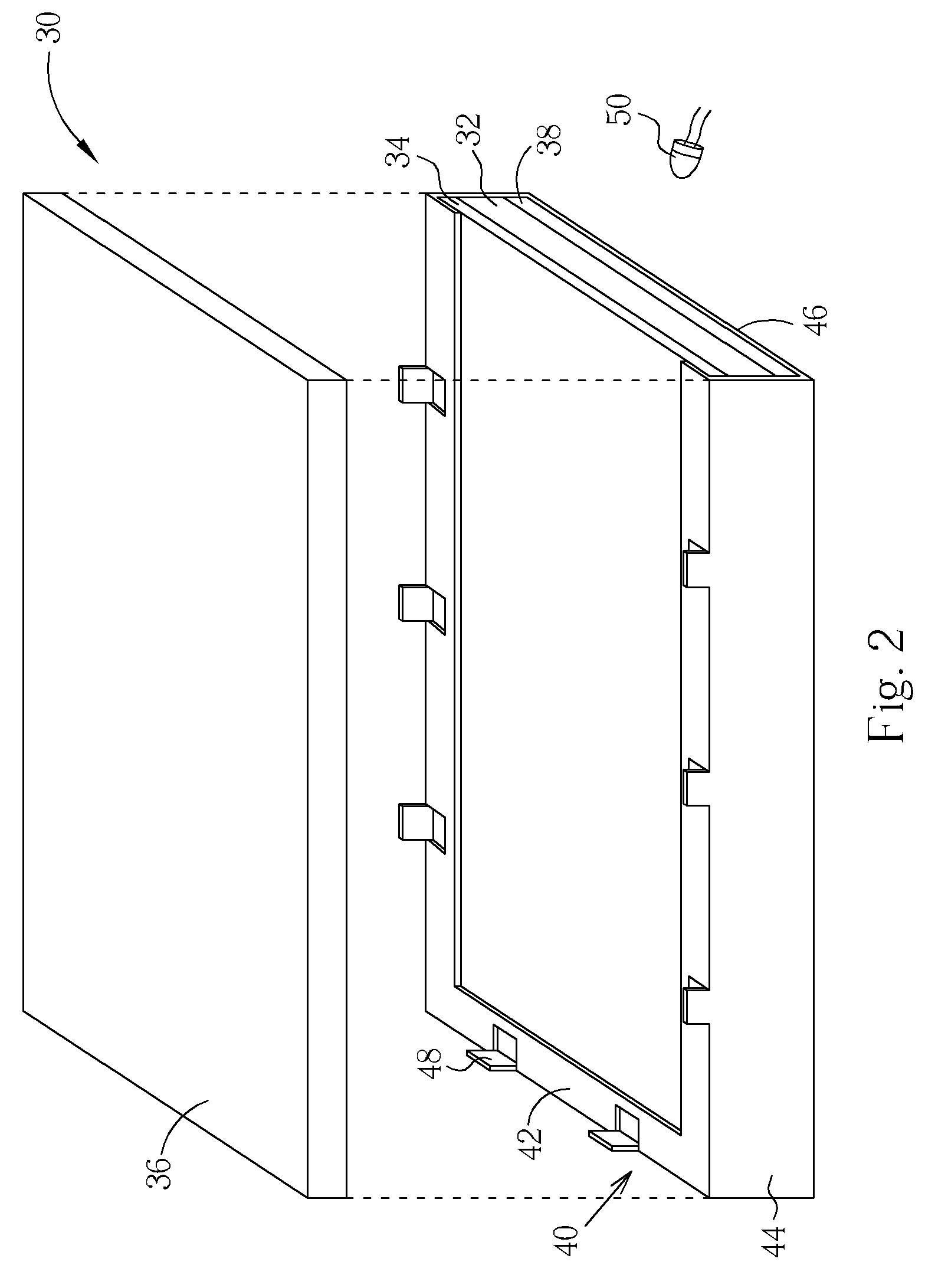
[0020] Please refer to FIG. 2, which is a diagram of a flat display module 30 of a first embodiment according to the present invention. The flat display module 30 comprises a light guide plate 32, an optical film 34, a reflecting sheet 38, and a flat display panel 36. The optical film 34 and the reflecting sheet 38 are respectively placed on the top and bottom of the light guide plate 32. It should be noted that the flat display panel 36 is an LCD panel. The optical film 34 can be a diffusion sheet, a prism sheet, or a combination of the diffusion sheet and the prism sheet. Furthermore, the flat display module 30 may comprise several optical films with different functions according to the design and demands of the whole flat display module 30. Please note that in FIG. 2, only one optical film 34 is shown for illustration purposes; this is not a limitation.

[0021] The flat display module 30 further comprises a fixing mechanism 40 partially covering the light guide plate 32, the optic...

Example

[0026] Please refer to FIG. 5 and FIG. 6. FIG. 5 is a diagram of a flat display module 100 of a fourth embodiment according to the present invention. FIG. 6 is a diagram of a single-side fixing mechanism shown in FIG. 5. As shown in FIG. 5, the flat display module 100 comprises a flat display panel 102, a light guide plate 104, an optical film 106, a reflecting sheet 108, and a plurality of single-side fixing mechanisms 110. The optical film 106 and the reflecting sheet 108 are respectively placed on the top and bottom of the light guide plate 104 while the flat display panel 102 is placed above the optical film 106. The single-sided fixing mechanism 110 comprises a top fixing surface 112, a bottom fixing surface114, a fixing sidewall 116, and a pane-fixing fragment 120, wherein the top fixing surface 112 and the bottom fixing surface 114 are connected to the fixing sidewall 116 in order to form a fixing cavity 118. The fixing cavity 118 is utilized for placing and fixing one side o...

Example

[0027] Please refer to FIG. 7, which is a flat display module 130 of a fifth embodiment according to the present invention. The flat display module 130 comprises a light guide plate 134, a plurality of optical films 132 placed on the top of the light guide plate 134, a reflecting sheet 136 placed on the bottom of the light guide plate 134, a flat display module (not shown) placed on the optical films 132, and a plurality of single-side fixing mechanisms 138 (in FIG. 7, only one single fixing mechanism 138 is shown).

[0028] The single-side mechanism 138 comprises a top fixing surface 140, a fixing sidewall 142, a bottom fixing surface 144, and a panel-fixing fragment 148 for fixing the flat display panel. The single-side fixing mechanism 138 further comprises a fixing plug 146. The top fixing surface 140 and the bottom fixing surface 144 respectively comprise a plug hole 140a and 140b for placing the fixing plug 146 through the top fixing surface 140 and the bottom fixing surface 144...


PUM


Abstract

A flat display panel comprises a light guide plate, a prism sheet, a LCD panel, and at least one fixing mechanism. The fixing mechanism comprises a top fixing surface, a bottom fixing surface, and a fixing sidewall forming a fixing cavity for positioning the light guide plate and the prism sheet. The fixing mechanism further comprises a panel-fixing fragment for fixing the flat display panel.

Description

BACKGROUND OF INVENTION [0001] 1. Field of the Invention [0002] The invention relates to a flat display module, and more particularly, to a flat display module comprising a specific fixing mechanism. [0003] 2. Description of the Prior Art [0004] The recent years and advancements in technology have seen light, power saving, portable, and smart information products play an increasingly important role in our lives. The flat display module is an important component of these products. The LCD display module has the advantages of low power consumption, small volume and no radiation pollution, thus the LCD display module has been widely utilized in notebooks, PDAs, cell phones and other portable information products. In addition, the LCD display module is gradually replacing CRT monitors and traditional TVs. [0005] Please refer to FIG. 1, which is a cross-sectional diagram of an LCD display module 10 according to the prior art. As shown in FIG. 1, the LCD module 10 comprises an LCD panel 1...

Claims


Application Information

Patent Timeline
IPC IPC(8): G02F1/1333G02F1/13G02F1/133G02F1/13357G09F9/00H04N5/645
CPCG02F1/133308G02F1/133615G02F2201/46G02F2001/133322G02F2001/133314G02F1/133314G02F1/133322
Inventor HUANG, CHANG-YUYU, CHUAN-PEI
Owner INNOCOM TECH SHENZHEN
Why Eureka
Try Eureka