Handover method

a handover and registration process technology, applied in the field of handover methods, can solve the problems of inability to substantially implement a router, inability to achieve substantial implementation, and inability to induce unacceptable handover latency, so as to reduce handover latency

Inactive Publication Date: 2006-02-09
ELECTRONICS & TELECOMM RES INST
View PDF7 Cites 65 Cited by
  • Summary
  • Abstract
  • Description
  • Claims
  • Application Information

AI Technical Summary

Benefits of technology

[0016] It is an advantage of the present invention to provide a handover method reducing handover latency in a less than 64-bit MAC address system including a 48-bit IEEE address to automatically reserve addresses for a handover in mobile IPv6.
[0017] In one aspect of the present invention, in a handover method of the IPv6 (Internet protocol version 6), a mobile node receives a Layer 2 trigger message. The mobile node requests information on Layer 3 of a new access router (NAR) from a previous access router (PAR) by using information included in the Layer 2 trigger message, receives information on an IP address of the NAR and a new Care of Address (NCoA) to be used when moving to the NAR, and performs registration with a Home Agent (HA) and sends the binding update to a correspondence node using the NCoA when a Layer 2 handover is occurred.
[0018] The mobile node requesting the information on the Layer 3 of the NAR requests the information on the Layer 3 of the NAR from the PAR by using a MAC address of the NAR included in the Layer 2 trigger message.
[0019] The NCoA comprises a prefix informa

Problems solved by technology

A delivery interval of the Router Advertisement message is set to be 30 ms to 70 ms in the mobile IPv6, but it is difficult to be substantially implemented by a router.
Further, similar to the mobile IPv4, the mobile IPv6 is designed to support mobility in a wide area, and thus handover latency during a registration process may be an obstacle for to support a real-time service including a VoIP (Voice Over IP) which will be an essential part of the Internet in the near future.
The mobile node in the conventional mobile IP is required to register its new CoA with an HA which may be located away whenever the mobile node moves, and thereby inducing unacceptable handover latency.
Such a fast handover method may reduce the handover latency by creating a NCoA which may increase the handover latency and perform

Method used


Image

  • Handover method
  • Handover method
  • Handover method

Examples


Embodiment Construction

[0034] In the following detailed description, only certain exemplary embodiments of the present invention are shown and described, simply by way of illustration. As those skilled in the art would realize, the described embodiments may be modified in various different ways, all without departing from the spirit or scope of the present invention. Accordingly, the drawings and description are to be regarded as illustrative in nature, and not restrictive There may be parts shown in the drawings, or parts not shown in the drawings, that are not discussed in the specification as they are not essential to a complete understanding of the invention. Like reference numerals designate like elements.

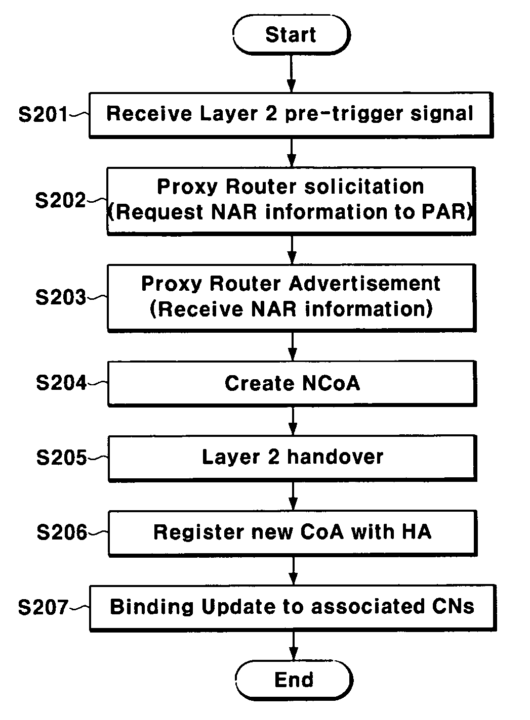
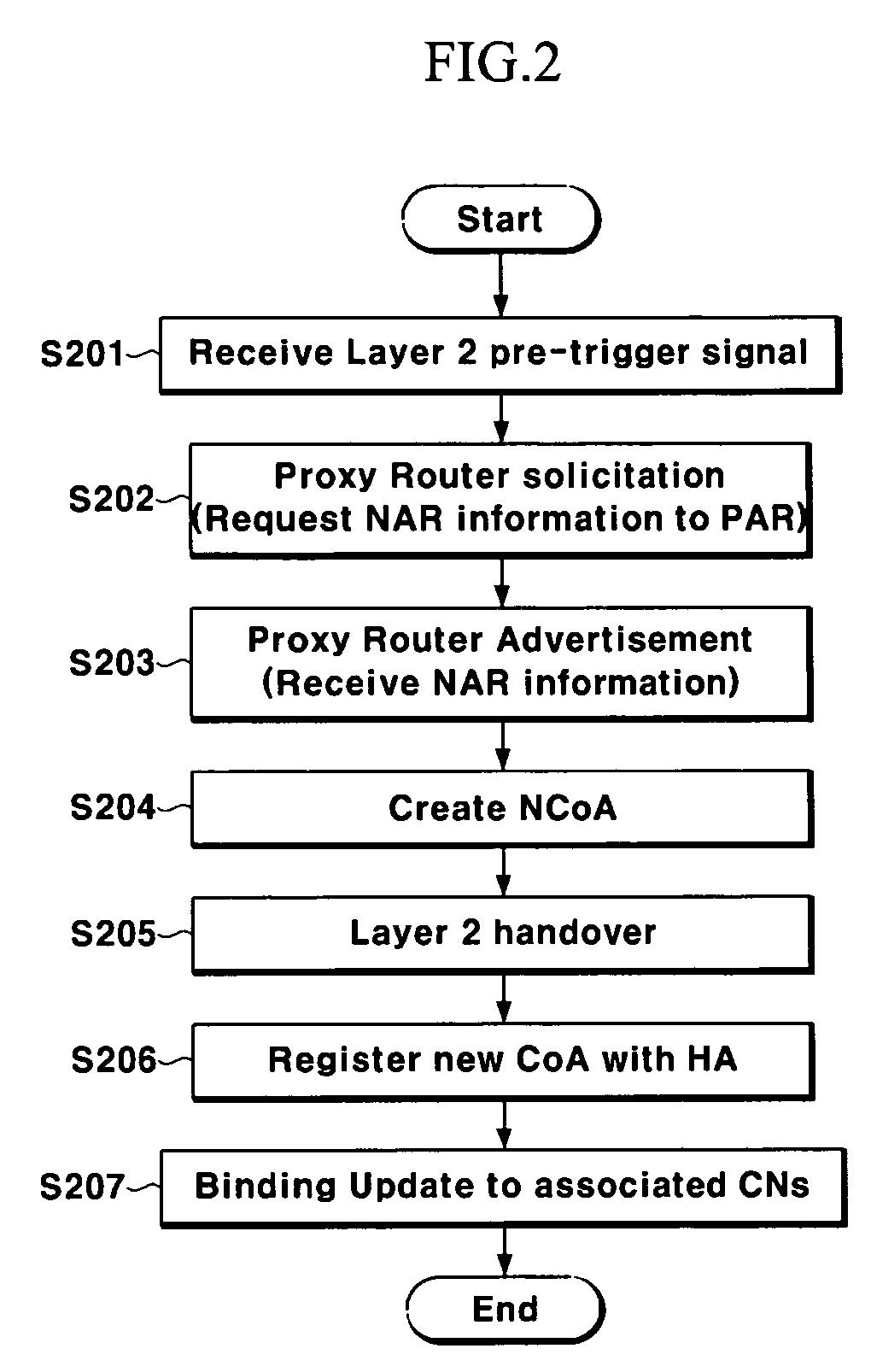
[0035] First, a schematic handover process according to an embodiment of the present invention will be described in detail, referring to FIG. 2.

[0036] As shown in FIG. 2, a mobile node according to the embodiment of the present invention receives a Layer 2 trigger message pre-notifying an occurren...


PUM


Abstract

In a handover method, a mobile node receives a Layer 2 trigger message; requests information on Layer 3 of a new access router (NAR) from a previous access router (PAR) by using information included in the Layer 2 trigger message and information on an IP address of the NAR and a new Care of Address (NCoA) to be used when moving to the NAR; and performs registration with a Home Agent (HA) of the mobile node and sending binding update to an associated correspondence node by using the NCoA when a Layer 2 handover is occurred. With this configuration, the present invention provides a handover method automatically creating an address using a MAC (Medical access control) address in the mobile IPv6 (Internet Protocol version 6).

Description

CROSS REFERENCE TO RELATED APPLICATION [0001] This application claims priority to and the benefit of Korea Patent Application No. 10-2004-61063 filed on Aug. 3, 2004 in the Korean Intellectual Property Office, the entire content of which is incorporated herein by reference. BACKGROUND OF THE INVENTION [0002] (a) Field of the Invention [0003] The present invention relates to a handover method, and particularly it relates to a handover method using a MAC (Media Access Control) address of less than 64 bits in a mobile IPv6 (Internet Protocol version 6) to automatically reserve addresses for a handover. [0004] (b) Description of the Related Art [0005] As the use of Internet has been explosively increased, the internet protocol IP (Internet Protocol) has lead technology on existing data networks and wired / wireless communication networks. Accordingly, standardization in networks has been accelerated under an AII-IP architecture forming an IP-based network: from a terminal to a core networ...

Claims


Application Information

Patent Timeline
IPC IPC(8): H04Q7/20H04W8/12H04W8/26H04W36/00H04W36/12H04W40/36H04W80/04
CPCH04W8/12H04W8/26H04W80/04H04W40/36H04W36/0016H04W36/24
Inventor JUNG, HEE-YOUNGLEE, JONG-HWALEE, HYEONG-HO
Owner ELECTRONICS & TELECOMM RES INST
Why Eureka
Try Eureka