Method for helical windmill artifact reduction with noise restoration for helical multislice CT

a technology of helical windmills and noise restoration, applied in the field of methods, can solve the problems of loss of image resolution, uneven noise, uneven noise, etc., and achieve the effect of preserving edges and background noise patterns

Inactive Publication Date: 2006-02-09
KK TOSHIBA +1
View PDF10 Cites 52 Cited by
  • Summary
  • Abstract
  • Description
  • Claims
  • Application Information

AI Technical Summary

Benefits of technology

[0006] Accordingly, in order to overcome the problems described above, the present invention is directed to a system, method,...

Problems solved by technology

The undesirable effect of slice thickening is that image resolution is lost.
This is undesirable from a clinical standpoint, especially when viewing images in a coronal or sagittal format.
The cause of the ...

Method used


Image

  • Method for helical windmill artifact reduction with noise restoration for helical multislice CT
  • Method for helical windmill artifact reduction with noise restoration for helical multislice CT
  • Method for helical windmill artifact reduction with noise restoration for helical multislice CT

Examples


Embodiment Construction

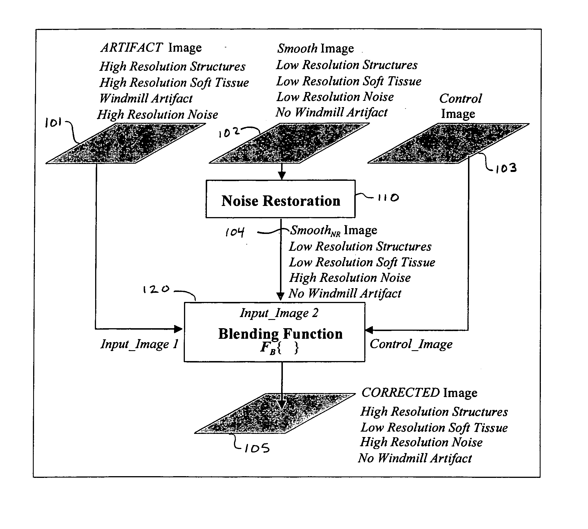
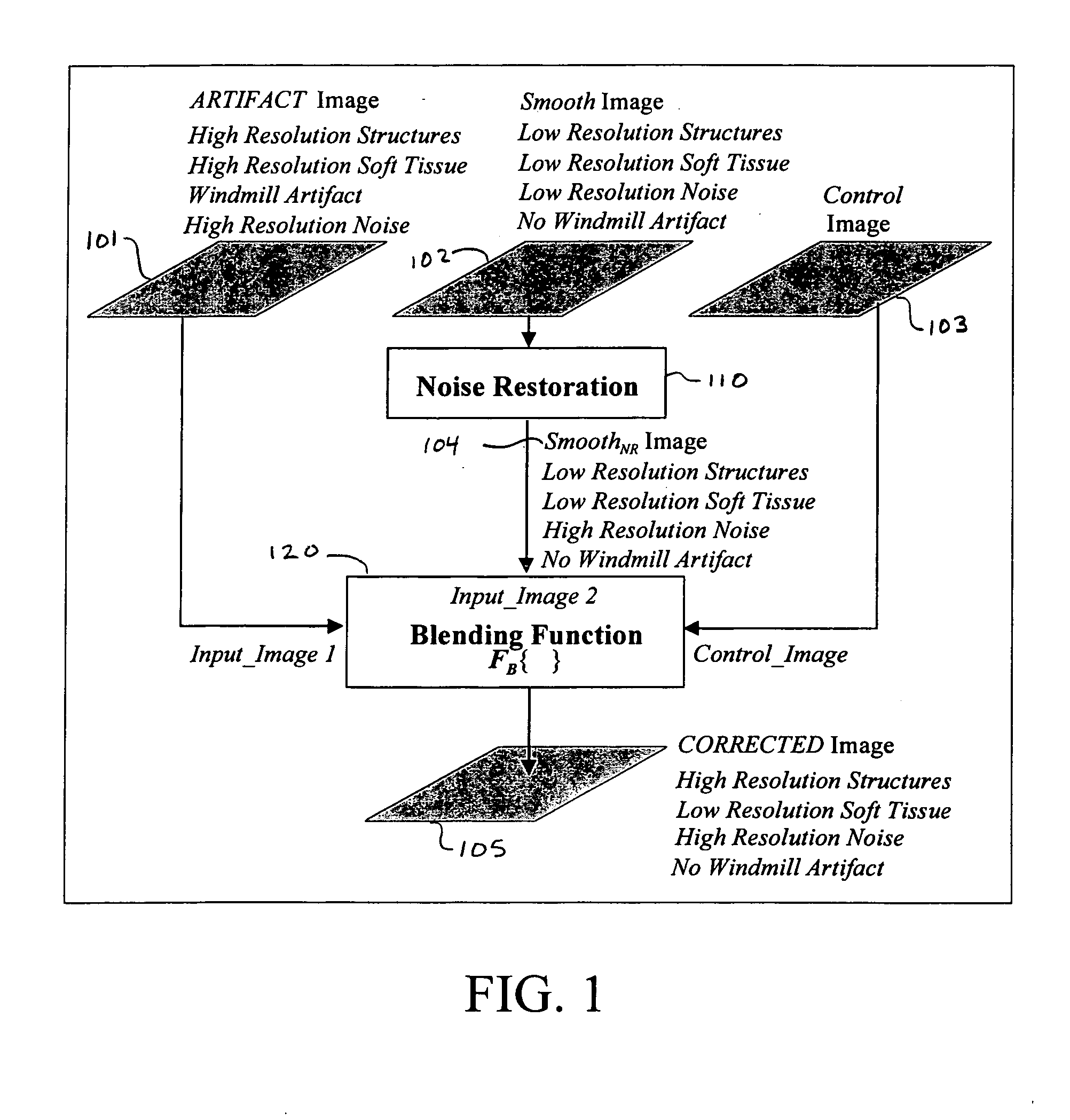
[0020] The present invention is directed to a system, method, and computer program product that corrects the windmill artifact and retains the sharpness of edges and background noise patterns. As shown in FIG. 1, an artifact image 101 and a smooth image 104 are combined to form a corrected image 105. This is accomplished by an adaptive blending of two input images, i.e., artifact image 101 and smooth image 104, where a control image 103 and blending function 120 (FB{ }) determine how the input images are blended. Further, smooth image 104 is the output of Noise Restoration Unit 110, which restores high resolution noise to smooth image 102, as shown in FIG. 1.

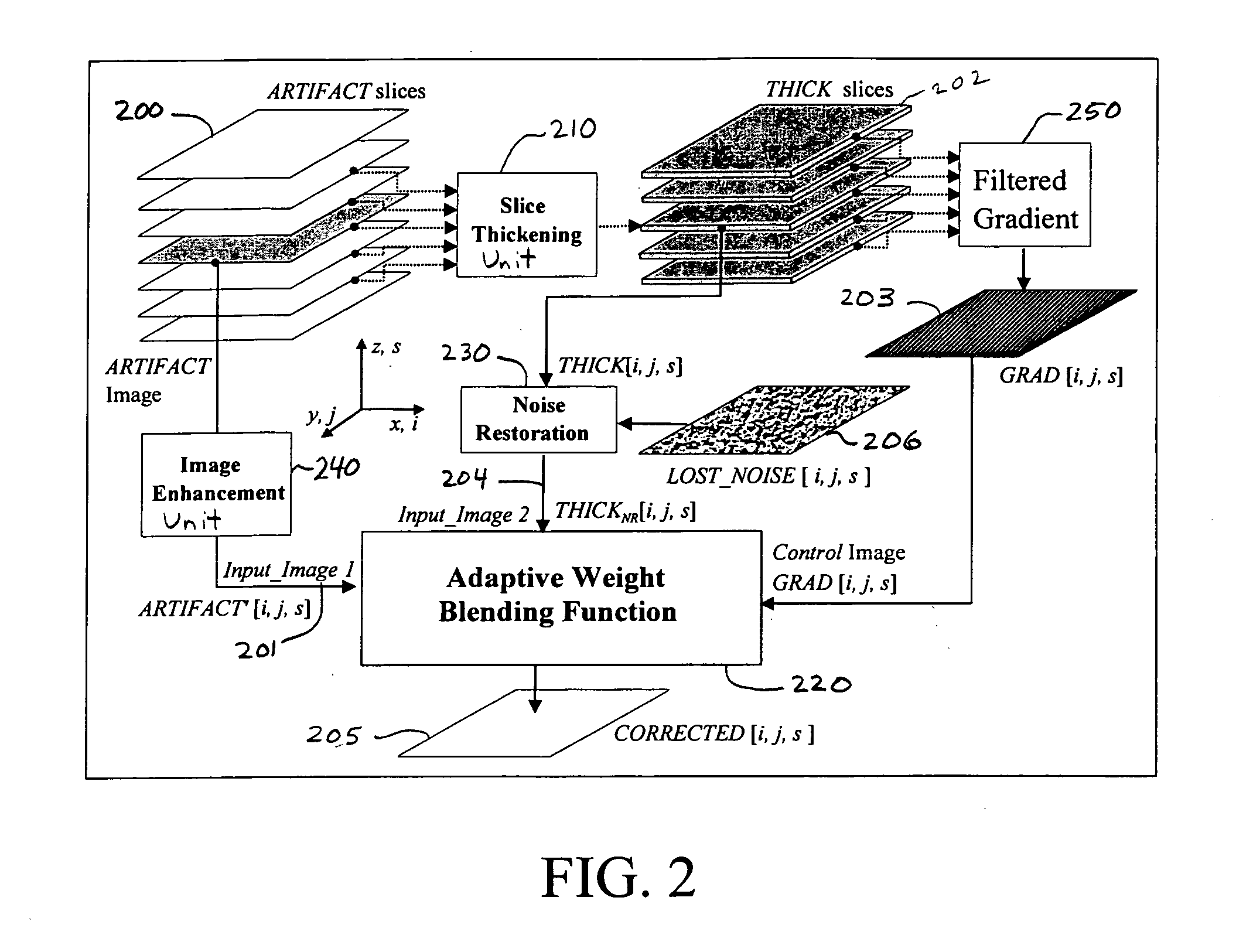
[0021] A system corresponding to the preferred embodiment of the present invention is shown in FIG. 2. Generally, the i and j indexes represent pixels in the lateral x and y directions, and the s index represents the slice position in the axial z direction. The input is the artifact image volume 200, which comprises a plurality...


PUM


Abstract

A method of removing an imaging artifact in a medical image, including obtaining a first plurality of images, the first plurality of images collectively defining a first image volume; filtering the first plurality of images to create a second plurality of images, each image in the second plurality of images comprising an average of at least two images in the first plurality of images; selecting a first image from the first plurality of images; adding a lost noise image to a second image in the second plurality of images to create a noise restored image, the second image in the second plurality of images corresponding to the first image in the first plurality of images; determining a gradient image based on pixel values in the second plurality of images, the gradient image comprising a gradient value at each pixel location in the second image; and combining, based on the determined gradient image, the first image and the noise restored image to obtain a corrected image that does not contain the imaging artifact.

Description

BACKGROUND OF THE INVENTION [0001] 1. Field of the Invention [0002] The present invention relates generally to the enhancement and filtering of medical images to remove artifacts. The present invention also generally relates to computerized techniques for automated analysis of medical images, for example, as disclosed in U.S. Pat. No. 5,825,842, which is incorporated herein by reference. [0003] 2. Discussion of the Background [0004] In X-ray CT imaging, it is common to low-pass filter or average a number of higher resolution images (“thin” images) in order to reduce artifacts or for other reasons. Typically, the filtering or averaging is performed in the axial direction, which is the direction perpendicular to the plane of the images (i.e., the z direction). The low-pass filtering is referred to as slice thickening because the effective “thickness” of the resulting image slice is larger. The undesirable effect of slice thickening is that image resolution is lost. This includes both ...

Claims


Application Information

Patent Timeline
IPC IPC(8): G06K9/40
CPCG06T5/50G06T2207/10081G06T2207/30004G06T2207/20221G06T5/002G06T5/003A61B6/027
Inventor HEIN, ILMAR A.TAGUCHI, KATSUYUKISILVER, MICHAEL D.
Owner KK TOSHIBA
Why Eureka
Try Eureka