Image forming apparatus

a technology of image forming apparatus and forming tube, which is applied in the direction of electrographic process apparatus, instruments, optics, etc., can solve the problems of severe so-called edge effect, unsatisfactory development performance of dc/ac bias development system, and toner to fly off, so as to reduce the occurrence of loss of image density

Inactive Publication Date: 2006-02-09
RICOH KK
View PDF50 Cites 108 Cited by
  • Summary
  • Abstract
  • Description
  • Claims
  • Application Information

AI Technical Summary

Benefits of technology

[0012] In view of the foregoing, an object of the present invention is to provide a process unit and image forming apparatus in which flying off of developer and occurrence of loss of image density are reduced.
[0013] A second object of the present invention is to provide a process unit and image forming apparatus in which flying off of developer and occurrence of loss of image density due to the edge effect, occurring as a by-product under developing conditions such as to enhance development performance are reduced, even in the case where a DC bias developing system is adopted.
[0014] A third object of the present invention is to provide a process unit and image forming apparatus in which it is possible to suppress unevenness of developing density produced by meshing impact of the teeth of adjacent gears in the drive system of the image forming apparatus and process unit.

Problems solved by technology

This is because, compared with the DC / AC bias development system, in which the toner tends to fly off during cycling between the developing roller and the photosensitive body, due to superimposition of an AC voltage on the DC voltage, in the DC bias development system, there are far fewer opportunities for the toner to fly off, since the electrical field acts unidirectionally from the developing roller to the photosensitive body.
However, the DC bias development system has unsatisfactory development performance compared with the DC / AC bias development system.
However, although making the linear speed ratio Vs / Vp large improves development performance, it results in a severe so-called edge effect, in which the amount of toner deposited at the edges of the electrostatic latent image on the photosensitive body is increased.
For example, if block regions are present in the halftone regions of the image, the halftone portions in the peripheral portion of the block regions are not developed, due to the edge effect, and so lose image density.
However, although development performance is improved by reducing the developing gap, the sliding frictional force with the photosensitive body produced by the magnetic brush is augmented, resulting in a severe edge effect as described above, with the result that loss of image density occurs due to the edge effect.
This has side-effects including loss of image density at the rear edge of the image, deterioration of reproducibility of transverse lines, and decreased life of the developer due to increased stress on the developer.
As a result, blurring of the rear edge portion of the image or loss of image density of peripheral portions of block images occurs.
Consequently, the problem arises that the rear edge portion of the image is blurred or the phenomenon of loss of image density of the peripheral portion of block images occurs, resulting in considerable loss of image quality.
Furthermore, as mentioned for example in Laid-open Japanese Patent Application No. 2003-240065, in recent years, in which the developing gap has been further narrowed, unevenness of density of development caused by minute vibrations of the developer carrier such as the developing roller have tended to become more noticeable.
Consequently, even if misalignment of axes of the rotary shafts of the gears in the drive transmission system of an image forming apparatus and the various process devices is cancelled, unevenness of development density tends to occur due to minute vibration of the developer carrier caused by factors other than such misalignment of axes.
However, in recent years, in which the width of the developing gap has been continually reduced, unevenness of developing density produced by such vibration has become serious.
A further problem is that unevenness of developing density is also produced by transmission to the image carrier of minute vibration caused by meshing impact of the teeth of adjacent gears in the drive transmission system of other image forming units, such as the photosensitive body, provided in the vicinity of the image carrier.

Method used


Image

  • Image forming apparatus
  • Image forming apparatus
  • Image forming apparatus

Examples


first embodiment

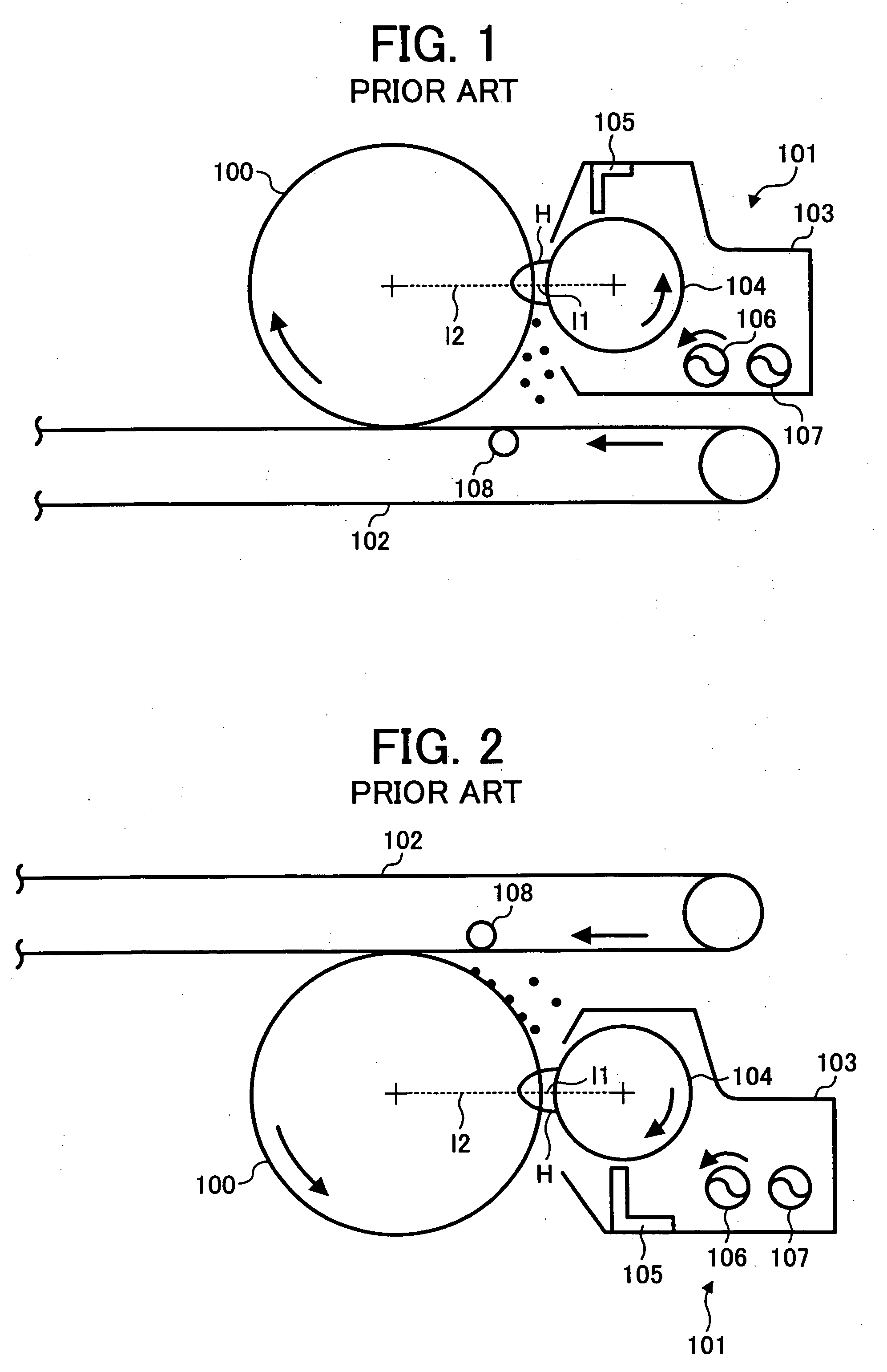
[0056] First of all, prior art relating to the first embodiment and problems thereof will be described.

[0057] As shown in FIG. 1, for example, conventionally, an image forming apparatus such as a copier, printer or facsimile machine comprises a drum shaped photosensitive body 100 that rotates in the direction of the arrow in the Figure, a developing device 101 arranged to the right in the Figure of the photosensitive body 100, and a transfer belt 102 arranged below the photosensitive body 100. The developing device 101 comprises, within a developing container 103 that is formed with an aperture facing the photosensitive body, 100 a developing roller 104 that carries developer in the developer container 103, a developer regulating member 105 that regulates the layer thickness of the developer on the developing roller 104, and developer feed members 106, 107 that stir and feed the developer in the developing container 104. The toner image that is converted to a visible image on the p...

embodiment 1

[0155] First of all, in a developing device as shown in FIG. 5, the amount of loss of image density in regard to developing magnetic pole angle and toner density under the developing conditions indicated below was measured. The results are shown in FIG. 9.

[0156] (Developing Conditions)

[0157] Linear speed of photosensitive body: 180 mm / sec

[0158] Linear speed ratio of photosensitive body and developing roller: variable range 0.5 to 3.0

[0159] Amount of developer picked up by the developing roller: 55 to 60 mm / cm2

[0160] Developing gap: variable range 0.25 to 0.50 mm

[0161] Toner: polymer toner as set out in this embodiment

[0162] Carrier: iron powder carrier of mass average particle size 35 μm

[0163] Toner density of developer: about 7 wt %

[0164] Developing bias: DC bias

[0165] Measurement of loss of image density was performed by the following method. The measuring device used was NEXSCAN F5100 manufactured by HEIDERBERG Inc. The degree of resolution set was 1200 dpi. A loss of i...

embodiment 2

[0174] Determination of the dependence of the developing performance on the developing gap and / or the linear speed ratio of the photosensitive body and developing roller was conducted under the same development conditions as in the case of embodiment 1. The results are shown in FIG. 11. The method of determination of the development performance was as follows. In general, the developing performance is usually expressed by the inclination of the amount of development deposition on the photosensitive body with respect to the developing bias i.e. the so-called development γ. The weight is measured by using a chart in which block patches of about 5 cm2 are sporadically distributed in the image, forcibly stopping the photosensitive body with the timing with which the toner has been developed onto the photosensitive body and using a suction method to suck up block areas left behind on the photosensitive body. The developing bias is taken along the horizontal axis and the amount of the dep...


PUM


Abstract

It is an object of the present invention to provide a process unit and an image forming apparatus in which generation of loss of image density due to flying off of developer and the edge effect occurring as a side-effect under developing conditions aimed at improving development performance can be reduced, even when a DC bias development system is adopted, and which can suppress developing density unevenness caused by impact occurring on contact of the teeth of gears in the drive system.

Description

BACKGROUND OF THE INVENTION [0001] 1. Field of the Invention [0002] The present invention relates to an image forming apparatus in which an electrophotographic system is adopted, such as copiers, printers or facsimile machines, particularly relates to an image forming apparatus in which a magnetic brush developing system using a two-component developer comprising a toner and carrier is adopted. [0003] 2. Description of the Related Art [0004] In image forming apparatuses in which an electrophotographic system is adopted, such as computers, printers or facsimile machines, an electrostatic latent image corresponding to image information is formed on a photosensitive body constituting an image carrier as disclosed for example in Laid-open Japanese Patent Application No. 2000-227690 and this electrostatic latent image is converted to a visible image by toner acting as developer within a developer device so that a toner image is obtained. In execution of this development process, in an im...

Claims


Application Information

Patent Timeline
Patent Type & Authority Applications(United States)
IPC IPC(8): G03G15/09
CPCG03G15/0898G03G15/0921G03G21/1857G03G21/186G03G2215/0609G03G2221/1633G03G2221/183
Inventor KASAI, TADASHIKIMURA, HIDEKIIMANURA, TSUYOSHIMASUDA, KATSUMIYOSHIZAWA, HIDEOSAKAI, KIYOTAKA
Owner RICOH KK
Why Eureka
Try Eureka