Radiopaque distal embolic protection device

a protection device and distal embolic technology, applied in the field of radiation-paque distal embolic protection devices, can solve the problems of particulate matter passing beyond the protection device, the protection device is not properly placed, and the difficulty of arising

Inactive Publication Date: 2006-02-09
EV3
View PDF30 Cites 111 Cited by
  • Summary
  • Abstract
  • Description
  • Claims
  • Application Information

AI Technical Summary

Benefits of technology

[0012] The present invention is intended for use in a lumen of a patient's body such as a blood vessel. Radiopaque filaments allow the filter to be viewed under fluoroscopy during a medical procedure. To achieve this, the filter is first advanced within the vascular system using the guidewire. The filter is maintained in a retracted configuration until properly positioned for deployment. Once the filter is deployed, the operator can ensure, in view of the radiopacity of the filaments, that the filter has properly engaged the lumen wall of the blood vessel and that the filter is properly sized for the blood vessel. Because the filaments are flexible and moveable with respect to each other, the filter is flexible and is deployable in diseased areas or within other non-uniform sections of a lumen such as a bend. Using fluoroscopy, an operator can ensure that the periphery has properly engaged an irregularly shaped lumen wall.
[0013] The present invention is configured and constructed so as to provide radiopacity to a deployable and retractable filter for ensuring the filter has engaged a lumen wall and assisting in recovery of the filter after the performance of a medical procedure.

Problems solved by technology

Difficulties can arise where the protection device is not properly placed within the lumen.
For example, if the periphery of the protection device does not fully engage the lumen wall, leaving a gap, then particulate matter might pass beyond the protection device.
Also, when the protection device is being advanced or withdrawn from the lumen it may engage with an obstruction.
One problem that can occur upon recovery is that the protection device may become engaged or otherwise obstructed by a stent or other jagged or ensnaring region that may be present within a blood vessel, such as a stenosis or an area of plaque build-up.
Another problem that can occur on recovery is that the protection device may not fully return to the retracted state due to a large amount of emboli and / or particulate matter captured within the protection device.
However, such disclosed devices have radiopaque marker bands mounted to a guidewire proximate the device and / or to struts of a frame of the device.
These devices do not employ a radiopaque filter structure, however, wherein mesh of a device basket is itself radiopaque.

Method used


Image

  • Radiopaque distal embolic protection device
  • Radiopaque distal embolic protection device
  • Radiopaque distal embolic protection device

Examples


Embodiment Construction

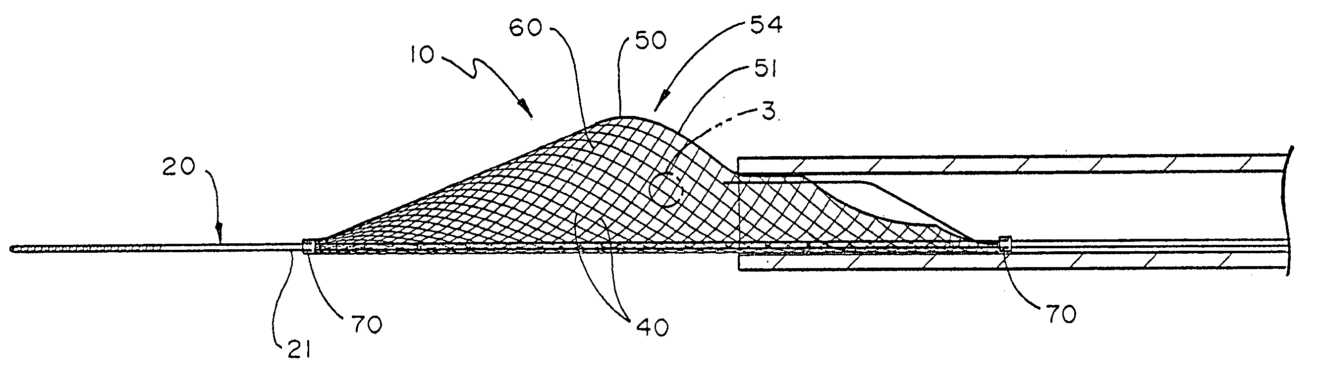
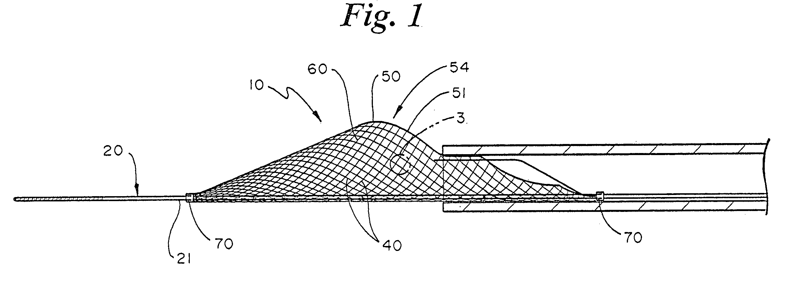
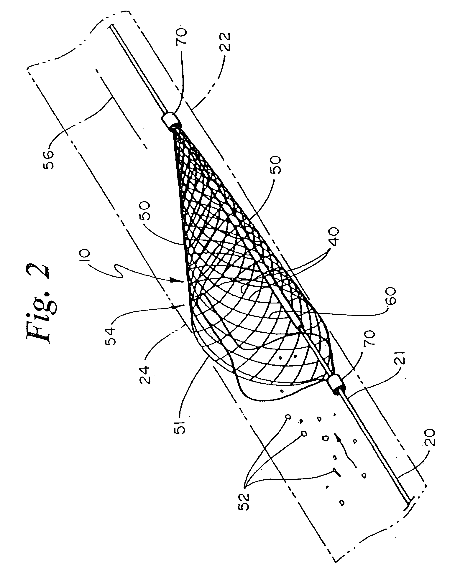
[0034]FIGS. 1 and 2 illustrate a protection device or filter 10 mounted to a guidewire 20. The guidewire 20 is an elongate member having a distal portion 21. The filter 10 is mounted at the distal portion 21 of the guidewire 20. The filter 10, shown partially deployed, may assume an expanded or a retracted configuration depending upon whether it is constrained by a catheter. In the expanded configuration, the filter 10 extends radially outward about an axis 56 to form a periphery. The periphery, illustrated at 50, is defined by the outermost portion of the filter 10. In the embodiment shown, a lip 51 is at least partially axially coincident with periphery 50 and defines a mouth to allow the capture of emboli 52 within the filter 10. The filter 10 may optionally have one or more radiopaque marker bands 70.

[0035] Suitable filters with respect to which concepts according to the present invention can be employed include those disclosed in WO 96 / 01591, U.S. Pat. No. 6,325,815, WO 01 / 156...


PUM

PropertyMeasurementUnit
diameteraaaaaaaaaa
diameteraaaaaaaaaa
thicknessaaaaaaaaaa

Abstract

The present invention is a radiopaque distal embolic protection device for use in a lumen of a patient's body, such as a blood vessel. The protection device has an expandable and retractable filter attached to a distal portion of a guidewire. At least a portion of the filter has a radiopaque coating for viewing under fluoroscopy during use. The radiopaque coating allows the operator to ensure that the periphery of the filter has fully engaged the wall of a blood vessel and to take appropriate measures in recovery of the protection device after capture of emboli and particulate matter.

Description

BACKGROUND OF THE INVENTION [0001] 1. Field of the Invention [0002] The present invention relates generally to the field of embolic protection devices and vascular filters. More specifically, the present invention relates to a radiopaque embolic protection device. [0003] 2. Description of Related Art [0004] Protection devices, such as embolic protection devices, are increasingly used in vascular intervention procedures. A protection device is an expandable and collapsible filter used to prevent the passage of particulate material, such as emboli, during a minimally invasive medical procedure. The protection device filter is moveably attached to a guidewire. In the collapsed configuration, the protection device can be advanced through a lumen of a patient's body, such as a blood vessel, to the treatment site. Once at the treatment site, the protection device is expanded such that the periphery of the protection device engages the wall of the lumen. Angioplasty, atherectomy, thrombect...

Claims


Application Information

Patent Timeline
Patent Type & Authority Applications(United States)
IPC IPC(8): A61M29/00A61F2/00A61F2/01A61L31/18
CPCA61F2/01A61F2250/0098A61L31/18A61L2430/36A61F2230/0093A61F2002/018A61F2230/0008A61F2230/0067A61F2230/0069A61F2002/016A61F2/0105
Inventor ANDERSON, KENT D.BADEN, JEANNINE B.HUETTL, KELLY J.KUSLEIKA, RICHARD S.
Owner EV3
Why Eureka
Try Eureka