Storage system and data processing system

Inactive Publication Date: 2006-02-09
HITACHI LTD
79 Cites 93 Cited by

AI-Extracted Technical Summary

Problems solved by technology

Furthermore, there is a problem in that, since a communications link between the first computer device and the first storage system is used to transfer the data, the data f...

Benefits of technology

[0008] Consequently, it is an object of the present invention to perform data transfer or data replication between a plurality of storage systems, without affecting the top-level computer device of the storage system. It is a further object of the present invention to avoid affecting communications between the storage systems and the computer device.
[0009] It is a ...

Abstract

A storage system comprises a data set storage region or storing a data set containing data and update data for managing this data, and a control section. The data set storage region is divided into a plurality of storage regions including a first storage region and a second storage region. The control section generates a first data set containing first data and first update data which is update data for same, stores at least the first data of this first data set in the first storage region, generates a second data set containing second data and second update data which is update data for same, and stores at least the second data of this second data set in the second storage region, which is separate from the first storage region.

Application Domain

Technology Topic

Image

  • Storage system and data processing system
  • Storage system and data processing system
  • Storage system and data processing system

Examples

  • Experimental program(5)

Example

Embodiment 1
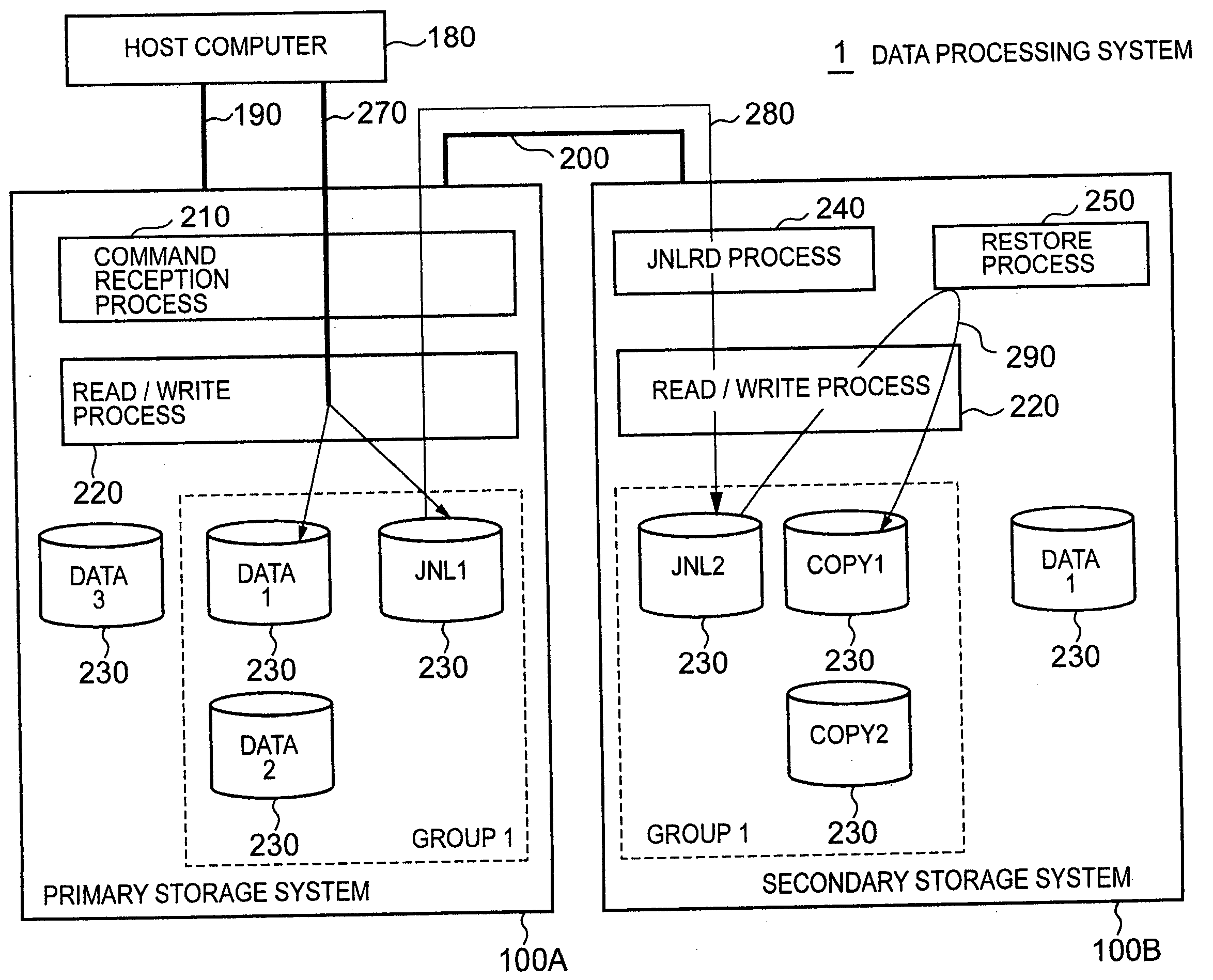
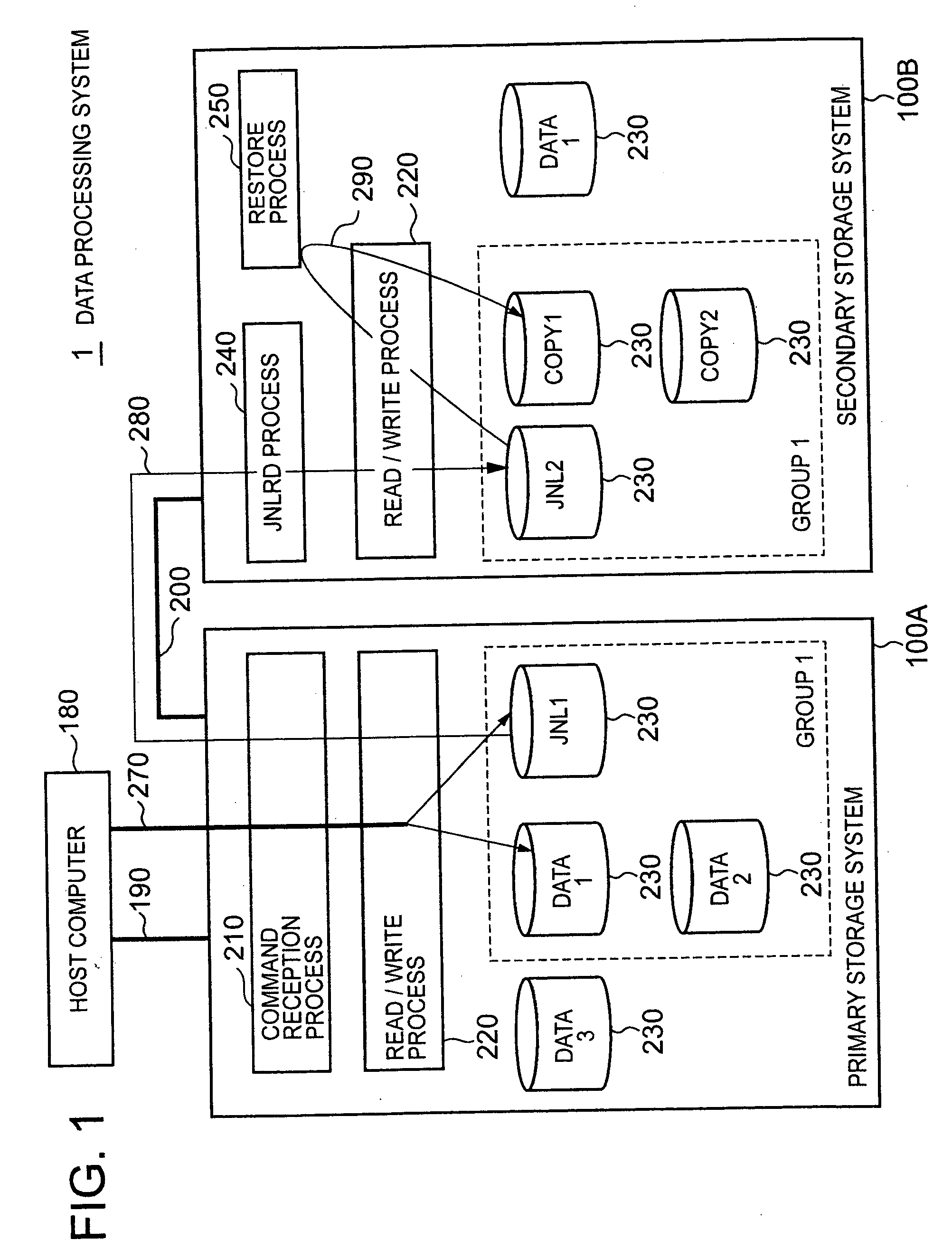
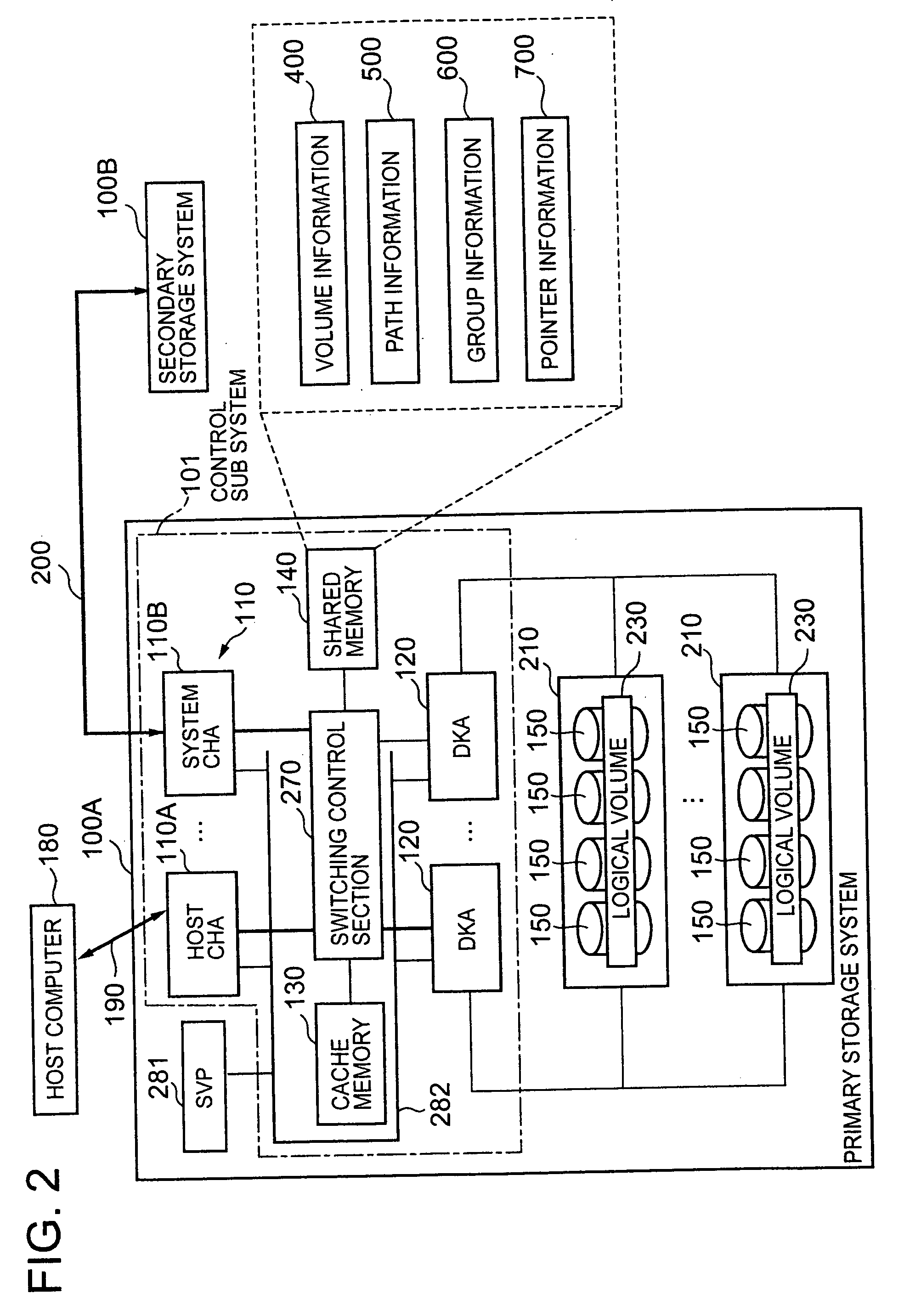
[0233]FIG. 23 shows an overview of a compositional example of a data processing system relating to a first embodiment of one mode of implementing the present invention. The following description focuses principally on the points of difference with respect to the aforementioned mode of implementation, and points which are common with the aforementioned mode of implementation are explained briefly or omitted from this description. Moreover, in the following description, the reference numeral 101A is appended to the control sub-system of the primary storage system 100A, and the reference numeral 101B is appended to that of the secondary storage system 100B. Moreover, the volume information, path information, group information and pointer information provided in the primary storage system 100A contain information relating to the primary storage system 100A, and are appended with the suffix A. At least one of the volume information 400A, the path information 500A, the group information 600A and the pointer information 700A may be located in the control sub-system 101B, and similarly, at least one of the volume information 400B, path information 500B, group information 600B and pointer information 700B may be located in the control sub-system 101A. Moreover, in this case, if one of the information elements is updated (for example, the path information 500A), then the updated contents may be reflected in the same information (for example, path information 500A) held in the other control sub-system, by means of the connection path 200. Moreover, the volume information, path information, group information and pointer information provided in the secondary storage system 100B contain information relating to the secondary storage system 100B, and are appended with the suffix B. In FIG. 23, the “#” symbol in a logical volume indicates the logical volume number. Moreover, the reference symbol “P” is appended to the primary logical volume (shown as “P-VOL”), the reference symbol “S” is appended to the secondary logical volume (shown as “S-VOL”), the reference symbol “A” is appended to the journal logical volumes in the primary storage system 100A (shown as “JNLVOL”), and the reference symbol “B” is appended to the journal logical volumes in the secondary storage system 100B. Below, when referring to a logical volume, in order to make the description easier to understand, a combination of the # appended to the logical volume and the aforementioned reference symbol will be used, instead of reference numbers such as “230”.
[0234] A plurality of journal logical volumes, for example, three journal logical volumes, #1A, #2A and #3A are included in a particular group 102A of the plurality of groups established in the primary storage system 100A. Furthermore, the group 102 also contains one primary logical volume, #4P, for example, which is a logical volume where journals are not stored and only write data is stored.
[0235] A plurality of journal logical volumes, for example, three journal logical volumes, #1B, #2B and #3B are included in a particular group 102B of the plurality of groups established in the secondary storage system 100B. Furthermore, the group 102 also contains one secondary logical volume, #4S, for example, which is a logical volume where journals are not stored and only write data is stored. In order to make the contents of the present embodiment easier to understand, the number of journal logical volumes contained in group 102A and the number of journal logical volumes contained in group 102B are taken to be the same, but these numbers may be different. Moreover, the respective storage capacities of the journal logical volumes #1A, #2A and #3A may also be different. The same applies to the journal logical volumes #1B, #2B and #3B.
[0236] If the control sub-system 101A has received a write command and write data for the primary logical volume #4P, from the host computer 180, then it stores the write data in the primary logical volume #4P in accordance with that write command. Moreover, the control sub-system 101A refers to the group information 600, ascertains the update number corresponding to the group number of the group 102A (hereinafter, also referred to as the “SEQ#”), and generates a journal containing the update number thus ascertained, and the like. The control sub-system 101A selects a first journal logical volume forming a storage destination for the update information in the journal, and a second journal logical volume forming a storage destination for the write data in the journal, from the plurality of journal logical volumes #1A, #2A and #3A. It stores the update information contained in the generated journal in the first journal logical volume thus selected, and it stores the write data contained in the generated journal, in the second journal logical volume thus selected. A more concrete description is given below.
[0237]FIG. 24 shows an example of the composition of the pointer information 700A in the first embodiment of one mode of implementing the present invention. FIG. 25 shows the composition of the pointer information 700A illustrated in FIG. 24, and this information is constituted in a plurality of journal logical volumes #1A, #2A and #3A. Below, the composition of the pointer information 700A in the primary storage system 100A and the plurality of journal logical volumes #1A, #2A and #3A are described with reference to FIG. 24 and FIG. 25, but this description can also be applied to the secondary storage system 100B.
[0238] Of the plurality of information elements in the pointer information 700A, the head address of the update information region, the head address of the write data region, the newest write data address and the oldest write data address are registered for each of the journal logical volumes located in the corresponding group.
[0239] According to the example in FIG. 24 and FIG. 25, the update information and the write data constituting the same journal are stored in a separate journal logical volume. More specifically, it is possible to store the update information and the write data respectively by means of the following methods, for example.
[0240] (Method for Storing Update Information in the Journal)
[0241] The control sub-system 101A selects a journal logical volume from the plurality of journal logical volumes, for example, the journal logical volume #1A having the most recent number, stores the update information 310 starting from the head position of the selected journal logical volume #1A, and then proceeds to update the information elements corresponding to journal logical volume #1 which are contained in the pointer information 700A, each time an update arises. Consequently, if the control sub-system 101A detects that the selected journal logical volume #1A has been used to the end of the update information region (the head address of the write data region), it selects a separate journal logical volume, for example, the journal logical volume #2A having the next most recent number, and stores the update information 310 from the head position of the selected journal logical volume #2A. Thereafter, similarly, if the storage region up to the end of the update information region (the head address of the write data region) in the journal logical volume #2 has been used, then the control sub-system 101A selects another journal logical volume, for example, the journal logical volume #3 and stores the update information 310 starting from the head position of this journal logical volume. If the storage region has been used up to the end of the update information region of journal logical volume #3 (up to the head address of the write data region), and there is no other unused journal logical volume, then the control sub-system 101A stores the update information 310 starting from the head position of the initially selected journal logical volume #1A. In storing the update information, the plurality of journal logical volumes may be selected in accordance with a previously determined sequence (for example, a sequence established in the shared memory 260, or the like), or it may be selected in a random manner. Furthermore, similarly to the method for storing write data described below, first and second update information having adjacent update numbers (for example, having consecutive update numbers) may be divided between separate journal logical volumes rather than being stored in the same journal logical volume.
[0242] (Method for Storing Write Data in the Journal)
[0243] The control sub-system 101A changes the journal logical volume forming the storage destination for the write data, for each journal. More specifically, for example, if there are N journal logical volumes (for example, 3 journal logical volumes) in the group 102A, the control sub-system 101A divides the update number in the update information forming a pair with the write data that is to be stored (for example, 5), by N (for example, 3), and stores the write data that is to be stored in the journal logical volume corresponding to the remainder value (for example, 2), namely, journal logical volume #2A. The storage destination address for the write data in the journal logical volume (for example, #2A) forms the newest write data address corresponding to that journal logical volume in the pointer information 700A. The first and second write data having adjacent update numbers are not necessarily stored in the same journal logical volume, but according to requirements, they may be stored in the same journal logical volume (for example, if the write data regions of the other journal logical volumes are full). Moreover, similarly to the update information storage method described above, the first and second write data having adjacent update numbers may be stored in the same journal logical volume, and if this journal logical volume becomes full, then they may be stored in another journal logical volume.
[0244] The foregoing description related to a method for storing the update information and the write data in the journal. If this storage method is adopted, the following processing can be carried out in the journal creation process (for example, step 1345 in FIG. 13 and step 1830 in FIG. 18) described in the aforementioned mode of implementation, for example.
[0245] The control sub-system 101A selects the journal logical volume forming the storage destination for the write data, from a plurality of journal logical volumes, and judges whether or not write data can be stored in that logical volume, on the basis of the various information elements corresponding to the selected journal logical volume (the information elements registered in the pointer information 100A). More specifically, for example, the control sub-system 101A divides the update number in the update information forming a pair with the write data that is to be stored (for example, 5), by the number of journal logical volumes N existing in group 102A (for example, 3), and it judges whether or not the write data can be stored in the journal logical volume corresponding to the remainder of this division operation (for example, 2), (namely, the journal logical volume #2A). If a negative judgment result is obtained, then the control sub-system 101A terminates the process as “failed to create journal” (step 1390 in FIG. 13, and step 1830 in FIG. 18). Rather than terminating the process, the control sub-system 101A may also search for a journal logical volume having sufficient free space to store the write data, on the basis of the data size of the write data and the pointer information 700A, and the like, and then store the write data in the free space of the journal logical volume found by this search.

Example

[0246] According to the first embodiment described above, a plurality of journal logical volumes are prepared for one group, and a first and a second write data having adjacent update numbers (for example, consecutive update numbers) are stored in separate journal logical volumes. Thereby, it is possible to make the writing of the write data overlap with the reading of the journal (in a “pipeline” fashion), and hence copying performance is improved. More specifically, if there is one journal logical volume, then the read (or write) performance for the write data is dependent on the performance of the storage device 150 providing that journal logical volume. In the present embodiment, a plurality of journal logical volumes are prepared and the write data in journals having adjacent update numbers is stored in different journal logical volumes. Therefore, it is possible to use a plurality of storage devices 150 simultaneously, and hence the journal read (or write) performance can be enhanced. In order to achieve such improved performance in a satisfactory manner, it is desirable that the plurality of journal logical volumes are provided in separate storage devices 150. Furthermore, if each journal logical volume is provided over a plurality of storage devices 150, then when providing a plurality of journal logical volumes, it is desirable that all or a part of the plurality of storage devices 150 providing one journal logical volume do not overlap with all or a part of the plurality of storage devices 150 providing another journal logical volume.
[0247] In the first embodiment described above, after step 1580 in FIG. 15 and before receiving a journal read command from the secondary storage system 100B, the control sub-system 101A may implement a read process autonomously in order to read one or more subsequent journals (in other words, the journal having the next update number onwards, in the journals sent at step 1580). Thereby, when the next journal read command is received, in the read process in step 1570 there will be an increased possibility that the journal corresponding to that command will already be situated in the cache memory 130, and therefore the time from receiving the journal read command until sending a journal to the secondary storage system 100B in accordance with that command can be reduced. Here “one or more subsequent journals” can be taken to mean journals up to the update number equal to the sum of previous update data plus the number of journal logical volumes, n, for example. In this case, in the secondary storage system 100B, the write data in the journal is stored continuously in the same journal logical volume.
[0248] Moreover, in the first embodiment, as described above, the first and second update information having adjacent update numbers (for example, consecutive update numbers), may be stored in separate journal logical volumes, similarly to the method for storing the write data.
[0249] Moreover, in this first embodiment, the plurality of journal logical volumes belonging to the same group do not have to have the same storage capacity.
[0250] Furthermore, in the first embodiment, it is also possible to implement the following, as a modification example.
(A) First Modification of First Embodiment
[0251] The control sub-system 101B of the secondary storage system 100B superimposes m journal read commands (where m is an integer of 2 or above) and it sends the m superimposed journal read commands to the primary storage system 100A. The control sub-system 101B inserts a number (hereinafter, called a “TAG#”) for identifying the journal read command in each of the m superimposed journal read commands. The TAG# ranges from 1 to m. More specifically, for example, if there are three superimposed journal read commands, then the control sub-system 101B inserts a TAG#1 into the first journal read command of the three superimposed journal read commands, inserts a TAG#2 in the second journal read command, inserts a TAG#3 in the third journal read command, and then sends the three superimposed journal read commands to the primary storage system 100A. In this case, in the primary storage system 100A, as illustrated in FIG. 26, specific information elements in the pointer information 700A (for example, the read start address and the retry start address) are provided in equal number to the number of superimposed commands, m, in other words, they are provided for each TAG#. The number of superimposed commands, m, may be the same as the number of journal logical volumes provided in the group 102A, for example. Furthermore, according to the pointer information 700A illustrated in FIG. 26, if the write data is read out from the journal logical volume #1A corresponding to TAG#1, then the read start address and the retry start address corresponding to the TAG#1 are the address “150” from the head position in logical volume number “1”.
[0252] A more concrete description of this first modification example is given below.
[0253] The control sub-system 101B of the secondary storage system 100B implements the journal read command processing illustrated in FIG. 17 for each TAG#.
[0254] When the control sub-system 101A of the primary storage system 100A has received a journal read command, it implements the journal reception processing described with reference to FIG. 15. In the journal reception process, the control sub-system 101A reads out the update information 310 from the logical address indicated by the retry start address and the read start address corresponding to the TAG# (the information elements included in the pointer information 700A) (steps 1570 and 1540). By means of the journal reception process, a journal containing update information is sent to the secondary storage system 100B. In this case, in order to identify the journal read command on the basis of which the journal was acquired, the control sub-system 101A appends the TAG# in the corresponding journal read command to the acquired journal and sends the journal with the appended TAG# to the secondary storage system 100B.
[0255] If the control sub-system 101B of the secondary storage system 100B receives a journal, then it implements the journal storage processing described with reference to FIG. 18. In this case, the control sub-system 101B calculates the logical address for storing the update information in the journal, on the basis of the TAG# and update number in the received journal and the pointer information 700B, and investigates whether or not update information can be stored in the journal logical volume identified by the TAG#, on the basis of the calculated logical address and the size of the update information (step 1810 in FIG. 18). Furthermore, the control sub-system 101B investigates whether or not write data can be stored in the identified journal logical volume, on the basis of the data size of the write data in the update information, and the pointer information 700B (step 1830 in FIG. 18). The journal logical volume where the update information and the write data are stored is the journal logical volume corresponding to the TAG#.
[0256] In this way, even greater copy performance can be achieved by sending journal read commands in a superimposed fashion.
(A) Second Modification of First Embodiment
[0257] The second modification is a further modification of the first modification example, wherein the primary storage system 100A acquires a plurality of journals and sends them to the secondary storage system 100B, in response to one journal read command. A more concrete description is given below.
[0258] In the journal reception process described with respect to FIG. 15, the control sub-system 101A of the primary storage system 100A acquires and sends the write data stored in consecutive storage regions of the same journal logical volume. More specifically, for example, in FIG. 25, the control sub-system 101A ascertains from the pointer information 700A, and the like, that the two write data registered in consecutive regions of the journal logical volume #1A correspond respectively to update number 1 and update number 4. Thereby, it generates update information including the update number 1 and a journal containing write data corresponding to same, and update information including the update number 4 and a journal containing write data corresponding to same, in response to one journal read command, and transmits them to the secondary storage system 100B. After the processing in step 1590 (or 1545) in FIG. 15, the control sub-system 101A determines the logical address for storing the two or more update information contained respectively in the two or more journals that are to be generated subsequently. In this case, the logical address is equal to the read start address plus the value obtained by multiplying the number of TAG#, m, by the update information size.
[0259] The control sub-system 101B of the secondary storage system 100B having received the journals implements the journal storage processing described with respect to FIG. 18, but in this case, the write data in the received journal is stored from the newest write data address in the journal logical volume corresponding to the TAG# appended to the received journal. In the example in FIG. 25, if the control sub-system 101B has received two journals having update number 1 and update number 4, then it writes the write data in the journal having update number 1 to the journal logical volume #1, starting from the logical address 700, and it then stores the write data in the journal having update number 4, in a continuous fashion following this write data.

Example

[0260] Next, a second embodiment of one mode of implementing the present invention will be described. The second embodiment is further example of application of the first embodiment described above. The following description focuses principally on the points of difference with respect to the aforementioned first embodiment, and points which are common with the aforementioned first embodiment are explained briefly or omitted.
[0261] In the second embodiment, the write data region in the journal logical volume is divided into a plurality of sub write regions. The plurality of sub write regions may respectively have the same storage capacity or they may have different storage capacities. In this second embodiment, they each have the same storage capacity. In other words, in the second embodiment, the write data region in the journal logical volume is divided equally into a plurality of sub write regions. Hereinafter, the individual sub write regions are called “extents”.
[0262]FIG. 27 shows an example of the composition of a plurality of journal logical volumes, #1A, #2A and #3A. FIG. 28 shows an example of the composition of extent information for managing a plurality of extents. FIG. 29 shows an example of the composition of pointer information 700A corresponding to FIG. 27 andFIG. 28. Below, a plurality of journal logical volumes #1A, #2A and #3A in the primary storage system 100A, the extent information 701 and the pointer information 700A are described with reference to FIG. 27 to FIG. 29, but this description can also be applied to the secondary storage system 100B.
[0263] As shown in FIG. 27, the write data region in the plurality of journal logical volumes #1A, #2A and #3A is divided equally into a plurality of extents (for example, four extents). An extent number for identifying the extent in the journal logical volume (for example, #0-#3) is appended to each of the extents in each of the journal logical volumes.
[0264] Moreover, as shown in FIG. 27, the write data regions of all of the journal logical volumes are also divided respectively into a plurality of extents, in a similar fashion. In other words, each of the journal logical volumes #1A, #2A and #3A has a write data region of the same storage size and containing the same number of extents. Therefore, at least the plurality of write data regions of the plurality of journal logical volumes #1A, #2A and #3A are each of the same size (the plurality of update information regions may each be of the same size, or of different sizes).
[0265] Furthermore, as shown in FIG. 27, the same extent number is not used twice in each individual journal logical volume, but in the plurality of journal logical volumes #1A, #2A and #3A (in other words, within the same group 102A), common extent numbers are used. More specifically, in each of the journal logical volumes #1A, #2A and #3A, there are four extents respectively labeled with the extent numbers, #0-#4. In other words, each write data region of each journal logical volume is divided into a plurality of sub write regions, and one extent is constituted by each sub write region of the plurality of journal logical volumes. Stated alternatively, by specifying one extent number (for example, #0), one sub write region is identified in each of the plurality of journal logical volumes #1A, #2A and #3A, and the set of identified sub write regions forms one extent corresponding to the specified extent number. Stated in yet another way, each extent extends over a plurality of logical volumes #1A-#3A belonging to the same group 102A.
[0266] An example of the composition of the extent information 701 for managing extents of this kind is illustrated in FIG. 28.
[0267] More specifically, the extent information 701 registers, for each extent #, which of the plurality of journal logical volumes #1A-#1C the extent corresponding to that extent # is located in. The location of the extent is indicated by a set comprising the start logical address and the end address, and such sets exist in equal number to the number of journal logical volumes #1A-#1C belonging to the same group 102A. The start logical address indicates the logical address at which storage of the write data starts, and end logical address indicates the logical address at which storage of the write data ends. Furthermore, in the extent information 701, the numbers #1-#3 registered respectively against the plurality of sets of start logical address and end logical address indicate the storage order of the write data.
[0268] It is possible to ascertain the following, for example, from the extent information 701 of this kind.
[0269] It can be seen that in the extent having the extent #0, initially, storage of write data starts from the address 700 in journal logical volume #1A, and if write data has been stored up to the position of address 1119 in volume #1A, then storage of write data subsequently starts from the position of address 700 in journal logical volume #2A. If the write data has been stored up to the position of address 1119 in journal logical volume #2A, then subsequently, storage of storage device is started from the position of address 700 in journal logical volume #3A.
[0270] It can be seen that in the extent having the extent #2, initially, storage of write data starts from the address 1200 in journal logical volume #2A, and if write data has been stored up to the position of address 1699 in volume 2A, then storage of write data subsequently starts from the position of address 1200 in journal logical volume #23A.
[0271] In this way, by changing the journal logical volume at which the storage of the write data starts initially, for each extent #, it is possible to cause all of the journal logical volumes #1A-#3A to function in parallel.
[0272] If write data is to be stored in the respective journal logical volumes #1A-3A on the basis of the extent information 701 described above, then the pointer information 700A will have the composition illustrated in FIG. 29. In other words, the head address of the update information region and the head address of the write data region are prepared for each journal logical volume #, and the newest write data address, the oldest write data address, the read start address and the retry start address are prepared for each extent #. By adjusting the newest write data address, the oldest write data address, the read start address and the retry start address, it is possible to write a plurality of write data having adjacent (for example, consecutive) update numbers, in separate extents.
[0273] In this second embodiment, the method for storing the update information is the same as that of the first embodiment, but the method for storing write data is different.
[0274] For example, for each journal, the control sub-system 101A changes the extent where the write data in that journal is stored. More specifically, if there are n extents (where n=4, for instance), then the control sub-system 101A divides the update number in the journal (for example, 12) by the number of extents (for example, 4), and stores the write data contained in the journal in the extent corresponding to the remainder of this division operations (for example, 0) (namely, extent #0). The storage destination address in that extent is the newest write data address corresponding to the number of the extent (the newest write data address registered in the pointer information 700A). The control sub-system 101A is able to detect whether the storage destination address has reached the end address (for example, address 1200) of one part of a certain extent (for example, #0) provided in a certain journal logical volume (for example, #1A), on the basis of the pointer information 700A and the extent information 701. Furthermore, in this case, the control sub-system 101A uses the extent information 701 to locate the start address of another part of the same extent provided in another journal logical volume that is to be set as the next storage destination address (for example, it determines that the address 700 of the journal logical volume #2A is to be the next storage destination address). The control sub-system 101A is then able to set this storage destination address as the newest write data address and store write data from that start address.
[0275] If this write data storage method is adopted, the following processing can be carried out in the journal creation process (for example, step 1345 in FIG. 13 and step 1830 in FIG. 18) described in the aforementioned mode of implementation, for example.
[0276] The control sub-system 101A divides the update number in the journal (for example, 12) by the number of extents, n, (for example, 4), and judges whether or not it is possible to store the write data contained in the journal, in the extent corresponding to the remainder of the division operation (for example, 0), (namely, the extent #0). If a negative judgment result is obtained, then the control sub-system 101A terminates the process as “failed to create journal” (step 1390 in FIG. 13, and step 1830 in FIG. 18). Rather than terminating the process, the control sub-system 101A may also search for a further extent having sufficient free space to store the write data, on the basis of the data size of the write data and the pointer information 700A, and the like, and then store the write data in the free space of the extent found by this search.
[0277] According to the second embodiment described above, the write data regions of the journal logical volumes are divided into a plurality of extents, and the write data in journals having adjacent (for example, consecutive) update numbers is stored in a distributed fashion in different extents. Thereby, it is possible to improve copying performance, regardless of the number of journal logical volumes belonging the same group (in other words, even if there is one journal logical volume in a group). For example, the time during which a storage device 150 cannot receive a read (or write) command can effectively be eliminated, and hence the performance of the storage device can be utilized more beneficially. In order to achieve such improved performance in a satisfactory manner, it is desirable that the plurality of journal logical volumes are provided in separate storage devices 150. Furthermore, if each journal logical volume is provided over a plurality of storage devices 150, then when providing a plurality of journal logical volumes, it is desirable that all or a part of the plurality of storage devices 150 providing one journal logical volume do not overlap with all or a part of the plurality of storage devices 150 providing another journal logical volume. Furthermore, it is also desirable that the plurality of extents are provided in separate storage devices 150.
[0278] In the second embodiment described above, after step 1580 in FIG. 15 and before receiving a journal read command from the secondary storage system 100B, the control sub-system 101A may autonomously implement a read process for the journal that is expected to be transmitted next. Thereby, when the next journal read command is received, in the read process in step 1570 there will be an increased possibility that the journal corresponding to that command will already be situated in the cache memory 130, and therefore the time from receiving the journal read command until sending a journal to the secondary storage system 100B in accordance with that command can be reduced. Here, the “journal that is expected to be transmitted next” can be taken to mean the journal having an update number equal to the previously processed update number plus the number of extents, p, for example. In this case, in the secondary storage system 100B, the write data in the journal is stored continuously in the same sub write region of the same journal logical volume.
[0279] Furthermore, in the second embodiment, the update information regions of the plurality of journal logical volumes (or the one journal logical volume) belonging to the same group may be divided respectively into a plurality of sub-regions (extents), in a similar fashion to the write data regions. In this case, the first and second update information having adjacent update numbers (for example, consecutive update numbers) may be stored in separate sub-regions (extents), similarly to the method for storing the write data.
[0280] Moreover, in the second embodiment, there is no limit on the number of extents, p, but in order to issue a read (or write) command to all of the journal logical volumes belonging to the same group, desirably, the number of extents, p, is equal to or greater than the number of journal logical volumes, n, (in other words, p>=n).
[0281] Furthermore, in the second embodiment, it is also possible to implement the following, as a modification example.
(A) First Modification of Second Embodiment
[0282] The control sub-system 101B of the secondary storage system 100B issues multiple journal read commands. The control sub-system 101B inserts an extent number into each of the superimposed journal read commands. The control sub-system 101B carries out the journal read command processing described with reference to FIG. 17, independently, for each extent number.
[0283] When the control sub-system 101A of the primary storage system 100A has received a journal read command, it implements the journal reception processing described with reference to FIG. 15. In the journal reception process, the control sub-system 101A refers to the pointer information 700A, and reads out the update information 310 from the logical address indicated by particular information elements corresponding to the extent number (namely, the retry start address and the read start address) (steps 1570 and 1540).
[0284] If the control sub-system 101B of the secondary storage system 100B receives a journal, then it implements the journal storage processing described with reference to FIG. 18. In this case, the control sub-system 101B calculates the logical address for storing the update information in the journal, on the basis of the extent number and update number in the received journal and the pointer information 700B, and investigates whether or not update information can be stored in the specified journal logical volume, on the basis of the calculated logical address and the size of the update information (step 1810 in FIG. 18). Furthermore, the control sub-system 101B investigates whether or not write data can be stored in the identified journal logical volume, on the basis of the data size of the write data in the update information, and the pointer information 700B (step 1830 in FIG. 18). The journal logical volume where the update information and the write data are stored is the journal logical volume corresponding to the extent. At step 1830 in FIG. 18, the control sub-system 101B may investigate whether or not write data can be stored in the extent corresponding to the extent number.
(B) Second Modification of Second Embodiment
[0285] The second modification is a further modification of the first modification example, wherein the primary storage system 100A acquires a plurality of journals and sends them to the secondary storage system 100B, in response to one journal read command. A more concrete description is given below.
[0286] In the journal reception process described with respect to FIG. 15, the control sub-system 101A of the primary storage system 100A acquires and sends the write data stored in consecutive storage regions of the same extent. More specifically, for example, in FIG. 27, the control sub-system 101A ascertains from the pointer information 700A, and the like, that the two write data registered in consecutive regions of the sub write region logical volume #1A correspond respectively to update number 8 and update number 12. Thereby, it generates update information including the update number 8 and a journal containing write data corresponding to same, and update information including the update number 12 and a journal containing write data corresponding to same, in response to one journal read command, and transmits them to the secondary storage system 100B. After the processing in step 1590 (or 1545) in FIG. 15, the control sub-system 101A determines the logical address for storing the two or more update information contained respectively in the two or more journals that are to be generated subsequently. In this case, the logical address is equal to the read start address plus the value obtained by multiplying the number of extents, p, by the update information size.
[0287] The control sub-system 101B of the secondary storage system 100B having received the journals implements the journal storage processing described with respect to FIG. 18, but in this case, the write data in the received journal is stored from the newest write data address in the extent corresponding to the extent number appended to the received journal. In the example in FIG. 27, if the control sub-system 101B has received two journals having update number 8 and update number 12, then it writes the write data in the journal having update number 1 to the journal logical volume #8, starting from the logical address 700, and it then stores the write data in the journal having update number 12, in a continuous fashion following this write data.

PUM

no PUM

Description & Claims & Application Information

We can also present the details of the Description, Claims and Application information to help users get a comprehensive understanding of the technical details of the patent, such as background art, summary of invention, brief description of drawings, description of embodiments, and other original content. On the other hand, users can also determine the specific scope of protection of the technology through the list of claims; as well as understand the changes in the life cycle of the technology with the presentation of the patent timeline. Login to view more.

Similar technology patents

Superposition coding

InactiveUS20100046644A1Reduce complexityImprove performanceMultiple modulation transmitter/receiver arrangementsSecret communicationSuperposition codingEngineering
Owner:MOTOROLA MOBILITY LLC

Vertical adaptive antenna array for a discrete multitone spread spectrum communications system

InactiveUS20050002440A1Improve performanceImprove signal-to-interference levelPolarisation/directional diversityMultiplex code allocationSpatially adaptiveSelf adaptive
Owner:AT&T MOBILITY II LLC

Classification and recommendation of technical efficacy words

Why Eureka
Try Eureka